Measurement
Why Dimensional Air Gages Work So Well
The air gage is unmatched in its ability to gage parts with hard to reach features that in some cases would be impossible with any other method.

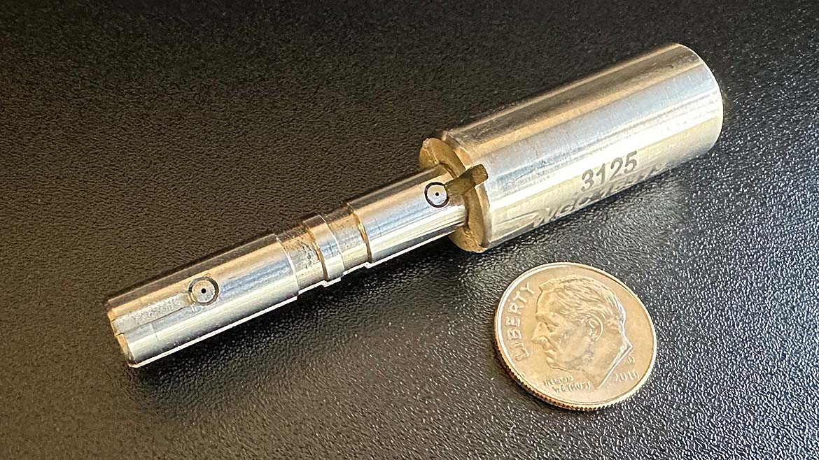
Figure 2 - Standard Air Probe for Measuring Inner Diameters Source: Western Gage Corp
Dimensional air gages have stood the test of time for over 80 years. The fact is, air gages are one of the best solutions when fast and accurate gaging is required, particularly for assessing size, form or runout of small deep holes gauged at the machine on the manufacturing floor. The reason for that is in the details.
Top three reasons why air gages work so well for these applications:
- They are of the body-piloting type
- They use the dual-opposing sensor method
- The sensing component is noncontact.
These three features are prominent in most air gage designs – particularly ID/OD air probe, air ring and air length gages.
Measurement
More on Air Gaging
Body-Piloting– notice that in the measurement of inner diameter, outer diameter or width, the form of an air gage takes the shape of the void space of the part to be measured. As an example, for the measurement of a machined hole - the body of the standard air gage is a cylindrical probe (Figure 2 above). For a part that is cylindrical in shape like a bar or rod, the form of the gage is a ring.
By matching the form of the gage to the void space of the part and incorporating a small clearance gap between the two, the gage’s body acts as a mechanical pilot in the sense that it guides and controls the spatial relationship between the gage and the part, and in turn, the position and orientation of the sensing elements (air nozzles) relative to the part. For air gaging, this gap can be as small as three tens-of-a-thousandths (.0003) of an inch (.0076 mm), which makes the gage self-restrained as it sits in or around the part. There is no need for operator control of its position – the body holds the sensing elements within a preferred range of the part, taking that burden and subjectivity off the operator.
The piloting action inherent to the body-piloted gage design also eliminates the need to seek the feature’s true dimension. On adjustable gages, such as a dial bore or telescoping bore gage, rocking is required to seek the minimum or maximum diameter (true size). Rocking is not required on body-pilot gages and that is extremely important for achieving fast and accurate measurements.
Dual-Opposing Sensor– Let’s break this down:
A simple dimensional measurement of diameter or length with an air gage is usually accomplished with two nozzles that are on opposite sides of the gage body – hence, “Dual Opposing.”
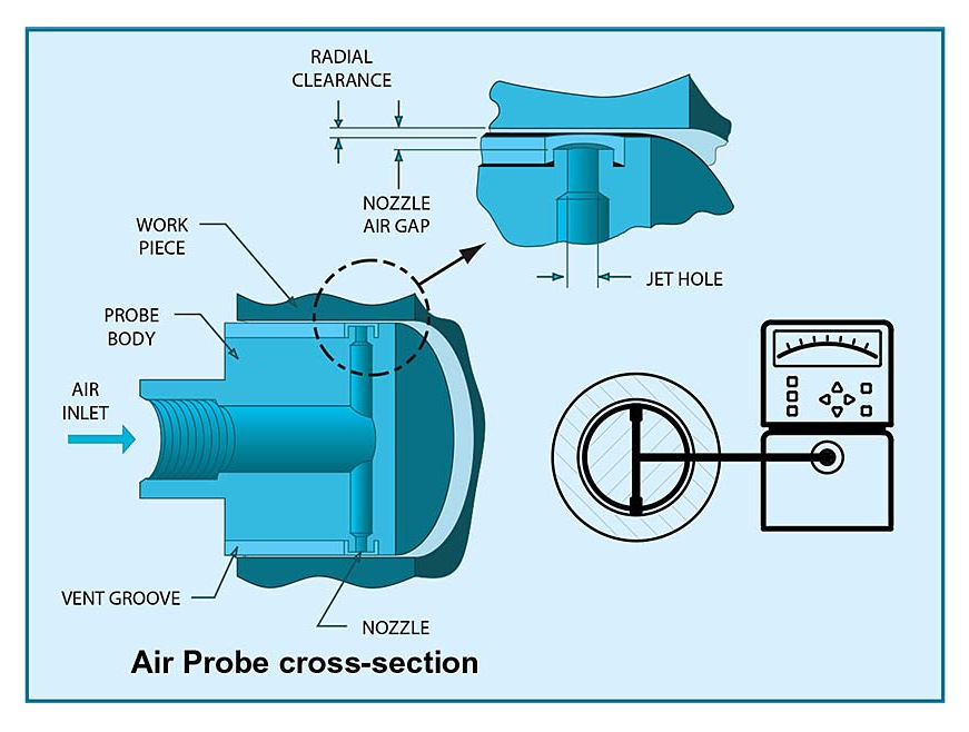
The body of an air probe, for instance, sits in the clearance space of the workpiece as in Figure 3. If the probe veers to one side the flow increases through the nozzle with the larger gap. The flow from the opposing nozzle decreases due to the smaller gap, counteracting the effect of position in the part. This action is much like a spring-loaded telescoping bore gage. Combine this with the body-piloted feature of the air gage, and the gage becomes insensitive to pitch, yaw, or lateral movement relative to the part.
The compressed air supplied to these nozzles is through small feed holes extending through the gage. This makes it possible to fabricate long thin probes that can reach deep inside holes. Multiple nozzles can be fabricated into one plug gage to make simultaneous measurements along a bore or at specific points on lands. The flexibility allows accommodation for many shapes and sizes as in the width gage of Figure 4.
Noncontact – don’t be misled here – the body of the gage makes contact with the part. This is a given, it is how it pilots the gage. What does not make contact are the nozzles. A properly designed air gage will have the face of the nozzle at a depth below the face of the body such that it cannot come in contact with the part. This is a great advantage when it comes to high usage and wear. The body takes all the wear and keeps the nozzles un-touched to maintain optimum performance over time.
Applications that Take Advantage of Body-Piloted, Dual-Opposing Nozzle, Noncontact Air Gages:
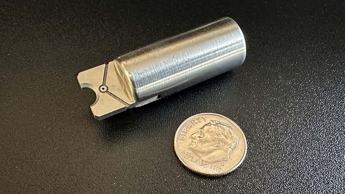
Rifling Gage (size)
The quality of the major and minor bore diameters on a rifled gun barrel can be inspected using the unique benefits of gaging with air. Rifling air probe gages are custom designed with a helical profile that matches the rifling on the inside of the barrel (Figure 5). In this respect, they are dedicated gages for a particular barrel specification. They are made to measure either the minor bore or the major groove diameters using long extension handles that penetrate deep inside the barrel. The helical profile of the gage maintains the sensor positions as the gage travels down the spiraling feature of the bore. Measurements can be made very quickly and with little operator skill.
Bore Straightness Gage (Form)
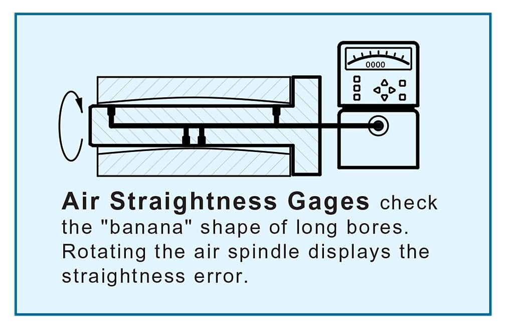
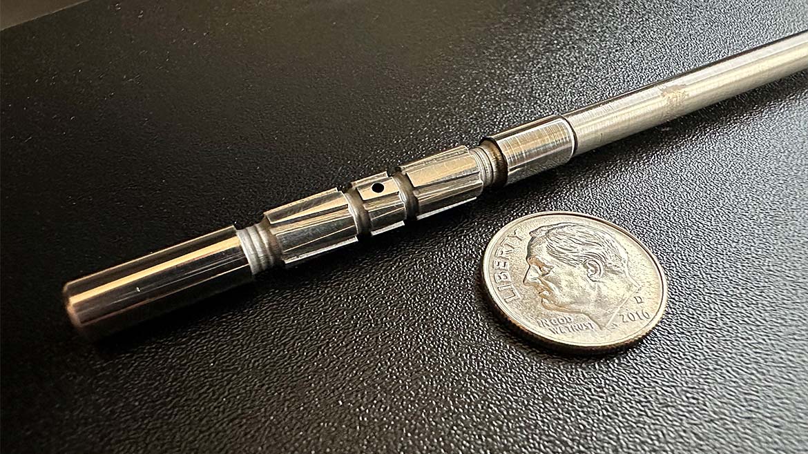
The straightness air gage is a clever approach to gauge not size, but form. Long “tube” like parts can be evaluated for bore straightness using air gages with body-piloted, opposed recessed nozzles. This type of gage uses three to four nozzles that are arranged in a way to sense camber (bowing) in the bore while being insensitive to size of the bore and tilt of the gage inside the bore (See Figure 6). Simply inserting the gage and rotating 360º to take a total indicator reading (TIR) will report twice the ASME/ANSI Y14.5 definition for straightness. Divide by two and you have your answer. A straightness air gage like that shown in Figure 7 makes for a quick and easy straightness measurement.
Runout Gage (Relationship)
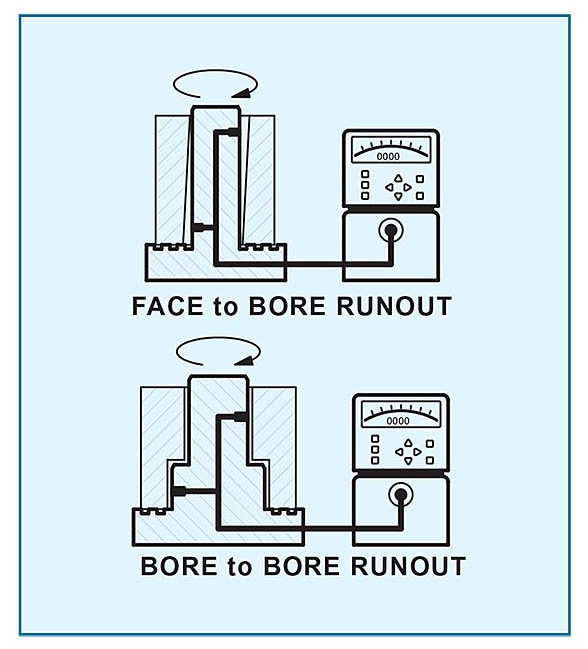
Runout relationships as shown in Figure 8 can be gauged with a special face-to-bore runout air gage, top image. These air gages use opposing jets that are staggered along the probe to evaluate squareness of the bore to the face. When the part is held flush with the face and rotated about the air gage, the sensing nozzles pick up wobble. These gages are insensitive to diameter size variation.
The same nozzle arrangement is used to gage parts with surfaces constructed around a datum axis as shown in the bottom image of Figure 8. Here an air gage measures cumulative variation of circularity and coaxiality.
In summary, the body-piloted air gage holds the sensing nozzles in a range where any movement of the gage is compensated for by the opposing arrangement of the nozzles. The nozzles are recessed to avoid any wear from contact with the part. With that, the air gage is unmatched in its ability to gage parts with hard to reach features that in some cases would be impossible with any other method available today.
How it Works…
A Dimensional Air Gage uses compressed air flowing from a nozzle to impart a stream of air jetting across a small gap to the surface of the workpiece to be inspected. As the gap between the nozzle face and the workpiece surface increases or decreases, the jet of air reacts with a change in flow and pressure. This change is sensed by the air gage Readout. The change in the air properties is directly proportional to the change in the gap. This phenomenon is how an air gage works.
Looking for a reprint of this article?
From high-res PDFs to custom plaques, order your copy today!


