Air Gaging: A Rich History in the Automotive Industry
One workhorse in the automotive industry is the bend and twist gage.
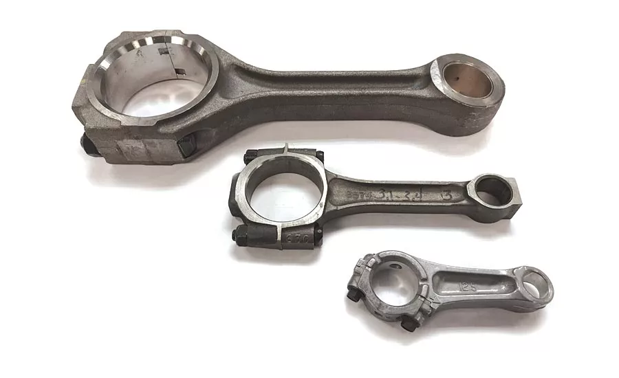
Figure 1 - Connecting Rods, an ideal application for air gaging
“Never before have mechanics and manufacturers, and in general has the world of industry, made use of gages and gaging systems as it is doing now. And there is a small wonder for this state of affairs, for these useful tools in all their different phases have proven to the satisfaction of the greatest mechanical economists of today that they are instruments that work for the reduction of cost of production, the perfect efficiency of products, and the education of, and increasingly the skill of, the productive worker,” wrote Joseph Vincent Woodworth in “Gages and Gaging Systems,” 1908.
This statement was printed 100 years after the beginning of the industrial revolution. Even as the statement is repeated today, more than 110 years after Woodworth inked the words in 1908, it is truer than ever, though perhaps not as grandiose.
Woodworth was describing the measuring instruments for achieving interchangeability and mechanization. His words preceded many inventions in use today such as computer numerical control, coordinate measuring machines, vision systems, scanners, lasers, SPC and air gages. It would not be long before clever inventions like the air gage would help drive the auto industry to new levels of efficiency and production.
The Bend and Twist Gage
Air gages have somewhat of a niche application—shop floor, handheld, ID/OD inspection being the most common usage. However, these gages find other useful applications when configured for measurement of geometric features and when applied to custom fixtures. One workhorse in the automotive industry is the bend and twist gage, illustrated in Figure 2. They are also referred to as rod checkers or rod alignment checkers. These gages measure dimensional and geometric features of engine connecting rods, or conrods, as shown in Figure 1. Conrods transmit the linear reciprocating power of the piston to the rotary motion of the crankshaft.
Connecting rods are critical components of the engine and require a high degree of dimensional accuracy. These requirements apply to newly manufactured rods as well as re-conditioned rods. On engine rebuilds it is often more economical to re-condition an out-of-spec connecting rod than to purchase a new one. This is especially true when talking about six to eight rods per engine. A frequent cause of a compromised connecting rod is over revving the engine, leading to dimensional distortion and loss of clearance for sufficient oil flow. Failure of a connecting rod is one of the most common causes of catastrophic engine failure.
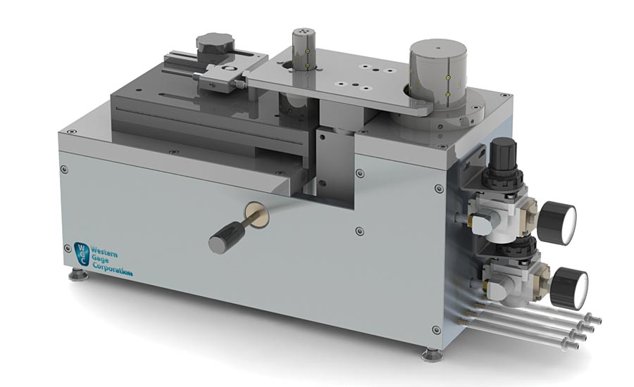
Figure 2 - Bend and Twist Air Gage Fixture
Conrods are inspected for parallelism of the piston-end and the crank-end bores (bend and twist), center distance, diameter, squareness, flatness of parting face, width, center distance of bolting hole, thickness of large end and small end, and roundness. These features must be in-spec for top performance of the engine and to achieve expected life. Of all the inspections required on a conrod, bend and twist are two of the most challenging without special fixtures or instruments.
The most common automotive connecting rod sizes range from 5” to 7” bore-to-bore center distance; 0.5 to 1.5” wrist pin end diameter and 2.0 to 2.5” crank end diameter. Bend and twist tolerances range from ±.0005” to ±.004”.
Figure 3 illustrates how a combination of air jets can be used to measure the bore-to-bore center distance and the parallelism in two planes between the crank bore and wrist pin bore. As can be seen, four jets are used to measure center distance and eight jets are used for each bend and twist gage. The circuits are combined and summed to achieve the desired measurement. With this arrangements of jets, the gage is insensitive to diametrical size and is also insensitive to movement of the rod in any horizontal direction. These attributes make length and parallelism measurements fast and easy and eliminate the variability associated with operator technique. Simplicity and speed are the hallmarks of the bend and twist air gage when it comes to high volume production.
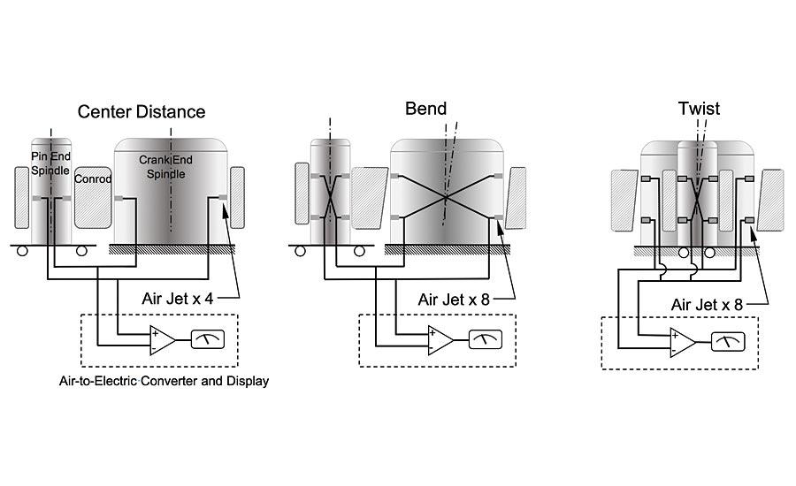
Figure 3 - Air Gage Configuration for Center Distance, Bend and Twist Measurement
Not to be overlooked are the other benefits of air gaging’s noncontact type measurement characteristic. The benefit of this is that the sensor does not experience wear, affording high repeatability and long life of the gage. Plus the high velocity stream of air cleans the part surface at the point of measurement.
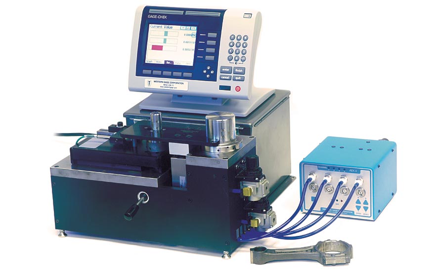
Figure 4 - Work Bench Size Bend and Twist Air Gage showing Air-to-Electric Converter and Display. Source: Western Gage Corp.
A workbench version of the bend and twist gage (Figure 4) is suitable for moderate to high volume inspection. These gages consist of a bend and twist fixture, air-to-electric converter and a display. They feature a platen with rest pads for the operator to seat the rod (Figure 5). The platen aligns the rod ends over the low clearance spindles for quick and easy loading. The rod and platen are lowered into place over the spindle by manual or pneumatic actuation. Variable type data are captured by activation of a button or foot switch. Data are recorded and results displayed on a user interface. These data are suitable for graphing and SPC analysis.
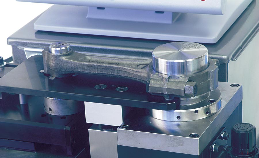
Figure 5 – Air Spindles with Conrod loaded and resting on Platen (a) ready for measurement.
The automotive industry has numerous families of connecting rods, resulting in many combinations of bore-to-bore center length, wrist pin diameter and crank end diameter. To accommodate the various conrod families, the small end spindle bore-to-bore center length is adjustable and both the large and small end spindles are interchangeable with spindles of suitable size to fit the rod diameters. An important feature for rods with large tolerances is the air bearings incorporated in the spindles. These air bearings act to center the rods, affording better measurement linearity (Figure 6).
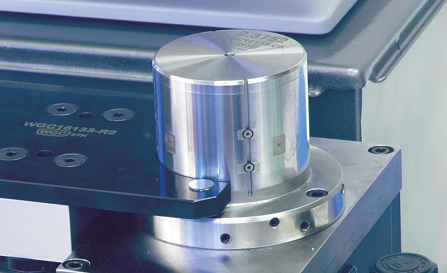
Figure 6 - Large End Air Spindle with (b) Air Jets; (c) Air Bearing; and (d) Platen Rest Pad.
Rick Warkentien, a manufacturing engineer at SRC Automotive, attributes the air gage to achieving their high production volume. “Air gaging has offered very low cycle times and good part family fixture change out,” he says. “These qualities are important in our high volume multi-family world.” Throughput of up to 800 rods per eight hour shift is achievable (Figure 7).
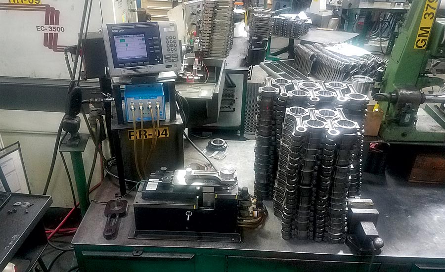
Figure 7 - Bend and Twist work station in a high volume production area. Source: SRC Automotive
The bend and twist air gage is one of the niche applications of air gaging. Its dedicated design to suit medium to high volume inspection of connecting rods affords it the perfect balance between affordability, accuracy and speed. Q
Looking for a reprint of this article?
From high-res PDFs to custom plaques, order your copy today!


