Test & Inspection
How to Improve Quality Control by Managing a Drifting Zero Point during Air Leak Testing
Why zero drift occurs and ways to mitigate or even eliminate it.

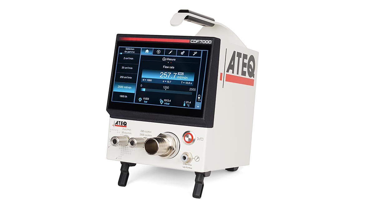
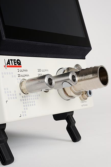
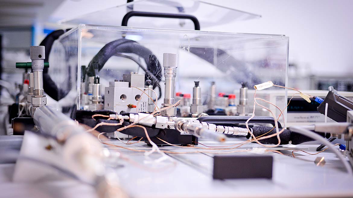
All Images Source: ATEQ
A common complaint from plant engineers and quality departments that are using air for leak testing is that the zero point will drift from zero during the course of the day. A drifting zero creates a quality control challenge. A common request is to find ways to minimize, or even better, eliminate any drifting zero and the need to constantly readjust the leak test instrument to compensate for drifts.
In the domain of industrial air leak testing for quality control, the “zero drift” phenomenon is accepted as a fact of life. “Zero drift” is when testing a non-leaking master device, the leak tester displays regularly a consistent non-zero reading and the leak test instrument needs to be readjusted. Changes in shop floor temperature are usually blamed for why a zero point will drift. This article is to help explain the reasons for why zero drift occurs and ways to mitigate or even eliminate it.
What Is Zero Drift?
We see examples of Zero Drift occurring in our everyday lives. Zero Drift means that the reading of an instrument on a non-leaking device under test is no longer at the expected zero value. A measurement taken with a Zero Point that has drifted will be suspect. Just like in the picture of the bathroom scale when no one is stepping on the scale it should not register a weight figure. The scale should return to zero. No one would trust a weight figure from a scale that started with a Zero that has drifted and started at a +3 or 5 pounds. The same can be said in industrial leak testing where a zero point has drifted, and you are measuring a leak rate.

What Is The Root Cause Of Observable “Zero-Drift”?
The root cause of zero drift is when the natural zero pressure drop is not reached within the time allowed for testing. A natural zero pressure drop means that a part with known zero/no leak experiences no pressure drop during the allowable time for the test.
Heat exchange is another reason for Zero Drift. If a test part changes temperature during the test, the pressure is directly impacted. This correlation can be seen in Boyle’s law PV=nRT.
The causes of “no natural zero” are multiple which means there is no miracle easy solution, and these include:
- Test Instrument Technology: The technology used in the test instrument contributes to Zero Drift.
- Test Fixture: The design of the test fixture will contribute to Zero Drift
- Application Design Related: The application can impact Zero Drift
- Inherent to the Test Part: Variability and other attributes of the test part impact Zero Drift.
- Maintenance: Lack of maintenance of the test instrument and fixture can create changes in the test operation contributing to Zero Drift.
- Environmental Factors: Changes in the environment that occur throughout the day influence the above and impact Zero Drift.

The causes of zero drift are explored further below.
1) Test Instrument Technology
Some instruments require regular adjustments because of the measurement and valve technology used. Examples of this type of measurement technology would be a heat exchange based mass flow sensor. Moreover, most gage or absolute pressure decay systems can be impacted by environmental changes.
Another example would be solenoid valves which will warm up during their normal operation. This warming of the solenoid valve will transfer heat and warm up the test circuit. This will also require an adjustment because the zero value has shifted.
Laminar flow meters with large pressure drops typically have a very long full response time. Most production applications demand short cycle times. The need for shorter cycle times will not allow the full long response time and the meter reading is taken while the meter is still unstable. This is commonly referred to as “lack of stabilization.”
2) Test Fixture Design
The design and construction of the test fixture can contribute to Zero Drift. These include:
- Porosity: Some people design test fixtures with inherently porous material in the test circuit such as wood, paper, 3D printed plastic, etc.
- Variable Volumes: A flimsy fixture design can expand during the test. Also, the use of push connectors has been shown to leak and the connectors move over time.
- Dead Volumes: “Dead Volumes” which are filled slowly like a thread without thread lock/glue, or unfilled cavities in your device that fill slowly act like a memory of previous tests.
- Hard Metal Stops: An air cylinder movement should be stopped on a hard surface if it pushes on a seal, in order to prevent any volume change during the test.
- Expanding Hoses: use of soft hoses can expand during testing.
Note: Best practices in test fixture design should also include minimizing the test volume (part of test tubing or of the volume of the device under test) where possible because it wastes fill and stabilization time.
3) Application Design Related
There are a number of application related items that can contribute to Zero Drift and test inconsistency.
- A Non-Differential Test: Even if you use a differential instrument, if the test and reference volumes are not balancing the effect of stabilization, more cycle time will be needed to reach a natural zero pressure drop for zero leak.
- Lack of a Fast Fill System: Filling too slowly leaves less time available for necessary stabilization.
- Reference Part Temperature Drift: The temperature of the reference part will change when exposed to repeated pressurizing/depressurizing the same reference part at high pressure.
Note: There are a number of methods to mitigate the above items.
4) Inherent To The Test Part
There are a number of contributing factors related to the test part itself which can contribute to testing inconsistencies with a relationship to Zero Drift.
- Test Part is at a different temperature than ambient: Best practices are to test parts at ambient temperature. Despite the best efforts to test devices at ambient temperature, some devices like castings and EV batteries are so massive that they are never exactly at ambient temperature. These differences of temperature affect the zero drift through a non-repeatable heat exchange.
- Stabilization due to adiabatic decompression/compression: Compressed air changes temperature if it decompresses quickly. During the stabilization time, there is a heat exchange. Changes in the temperature of the air inside the test part will cause a change in pressure.
- Stabilization due to Volume Expansion of the Test Part being tested: Some test parts expand when submitted to pressure because of their construction. This volume expansion creates a pressure drop not created by the leak. A large battery tray, while it is made of metal, the large size lends itself to volume expansion undertest. A plastic Balloon Catheter is another one example where the thin wall thickness allows for expansion under test. One complexity with thin-walled plastic test parts is that the degree of expansion changes depending on the test environment temperature. Therefore, a zero drift will happen if a zero offset has been applied to the test instrument to compensate for an expansion which can change over the course of the day, due to changes in test temperature.
- Another problem is that some devices do not behave/expand in the same way if they were tested before (like a memory of a previous test) so it becomes impossible to test the new test part with the same test settings as for a previously tested part. In addition, test parts where a leak was detected by the first leak test and the leaks were repaired cannot be tested like newly manufactured part. It is recommended to test these parts with “rework” settings. There is also an unpredictable production variability that creates differences in expansion between devices under test.
- Stabilization due to internal porosities or leaks into “dead volume”: Some devices are inherently porous like, for example, the charcoal in an automotive carbon cannister, the paper material in an oil filter. These porosities take a long time to fill and create a pressure drop which is not an external leak. Moreover, the porous material is frequently not repeatable in terms of porosity, creating a “zero drift.” The same problem happens when there is an internal volume that is not pressurized but there can be a leak into this volume (dead volume) adding to the actual leak. If the zero point was adjusted on a part with an internal leak and no external leak, a part under test could display a negative reading if it has no internal leak.
- Note: there is a possible method to mitigate this.
Maintenance: (cannot be improved with a longer cycle time): when the seals and gaskets on the test fixture become worn out even on the best designed test systems, and they need to be changed. Lack of regular maintenance can contribute to “zero drift.” That is a drift that you need to see to know when to change your seals.

Recommendations On How To Address “Zero-Drift”
The causes of zero drift can be mitigated and even eliminated. One easy method, but less practical, is to allow for longer cycle times. Because increasing cycle time is often not a viable option, there are other options available which include:
-
Test Instrument Technology: The technology used in the test instrument contributes to Zero Drift.
Solution Recommendation: Switching to a dual sensor leak tester where the leak test is measured by a differential pressure sensor will significantly reduce instances of zero drift. Where a single gage sensor must be used then it is recommended to climate control the test environment. The most common method for addressing a Zero Drift occurrence is to reset the zero point or perform what is called a Comp (Compensation) and Cal (Calibration). This action masks the root of the issue of why the Zero Drift occurred in the first place. The valves in the test instrument should also not generate/conduct heat or volume changes during the test.
NOTE: Dual Sensor Leak Testers are only slightly more expensive than a single sensor leak tester, yet they provide significant improvement in addressing Zero Drift and thereby improved test quality. -
Test Fixture: The design of the test fixture will contribute to Zero Drift
Solution Recommendation: Push connectors, soft hoses and use of porous material should be avoided in any test fixture design. Test Fixture Designs should also ensure no moving seals. Lastly the test fixture should be of a rigid design. -
Application Design Related: The application can impact Zero Drift
Solution Recommendation: Close inspection of the application should be considered relative to the items discussed herein. -
Inherent to the Test Part: Variability and other attributes of the test part impact Zero Drift.
Solution Recommendation: In many cases the stabilization can be improved with a longer cycle time. Temperature related issues associated with rapid changes in test air pressure can be mitigated by stepping down the test pressure in rigid tanks and allowing the test air temperature to return to near ambient. Lastly, issues associated with volume expansion can be resolved with a combination of improved leak tester technology and test methods. -
Maintenance: Lack of maintenance of the test instrument and fixture can create changes in the test operation contributing to Zero Drift.
Solution Recommendation: The leak test system should show you when the seals are worn out that they leak, and not require the user to make a software compensation (zero out) on those seals and gasket leaks. Seals and gaskets should be replaced per the recommended PM schedule or at the first instance of an issue.
Conclusion
The occurrence of Zero Drift as an unavoidable part of air leak testing is not true. There are proven methods for addressing zero drift at its source, with the most impactful being selection of the leak tester with a technology not prone to Zero Drift. Compensating for a drifting Zero point through zero rests or Comp/Cals does nothing to address why the zero point drifted and will need to be repeated numerous times. This action of resetting the zero point after a zero drift is equivalent to tending to a withering plant by painting the brown leaves green.
Lastly, experience and education make a big difference in coming up with strategies for addressing drifting zero and issues around test stabilization. To improve an air leak test involves a technical analysis by a true air leak test professional of what are the reasons for the zero drift, and a good leak or flow test instrument. A qualified applications engineer can help you with technical solutions that are applicable and can help.
Legal disclaimer:
This document is designed to help people to test with air pressure . This document does not remove or lessen the plant engineer’s responsibility for setting their test parameters and verify practically that the findings correspond to the purpose of their product.
Ateq, its employees, and its affiliates cannot be held responsible /liable for the consequences of an improperly set test system, or an improperly chosen test method.
Looking for a reprint of this article?
From high-res PDFs to custom plaques, order your copy today!


