Automatic Inspection of Industrial Gas Turbine Parts
How do you inspect such large, heavy and complex parts—with the required accuracy?
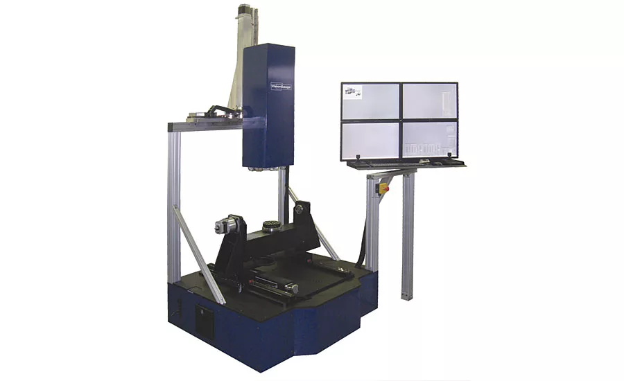
This 5-axis inspection system has extended 24” x 24”x 24” travel and trunnion configuration for big, heavy parts. Source: VISIONx
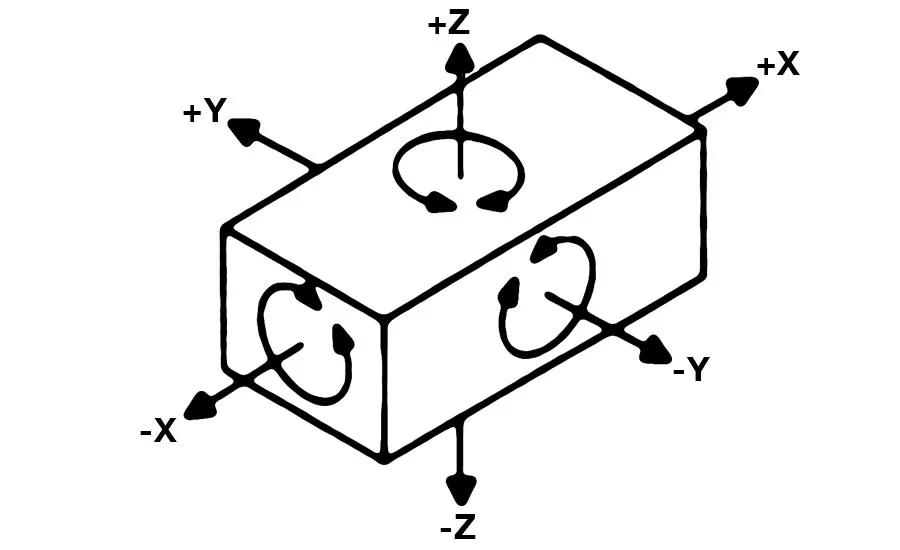
This digital optical comparator’s six-point iterative alignment tool accurately locates the six datum points on the part and mathematically “reorients” the part accordingly, along all of the part’s six degrees of freedom. Source: VISIONx
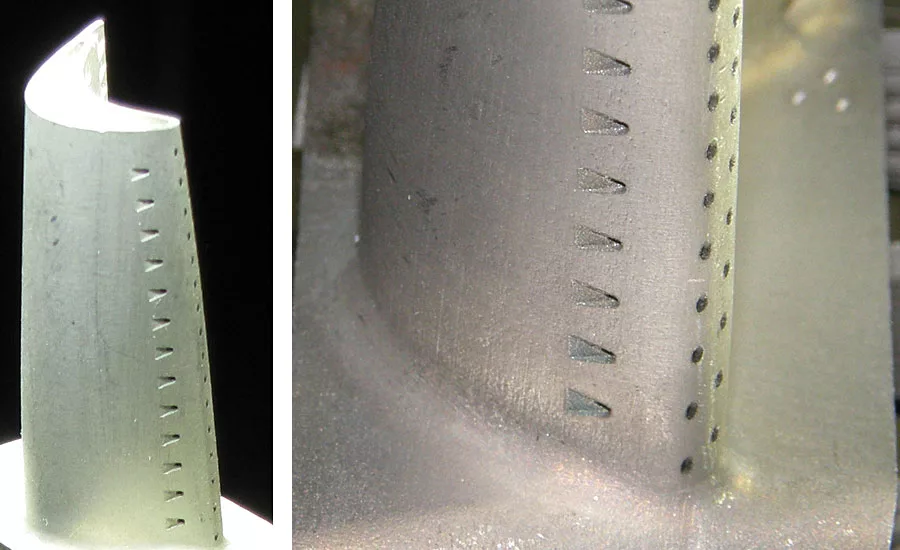
Automatically inspect both round and shaped holes anywhere on a part. Source: VISIONx
Many of the most critical parts that make up industrial gas turbines (IGTs) have complex 5-axis geometries and very tight tolerances. These parts undergo great stresses and extreme temperatures and it’s important that they be within tolerance to yield the expected performance. The first and most obvious reason is so they can all be properly assembled together. However, in this industry higher and higher efficiencies are being demanded. Power plants will only achieve maximum overall efficiency if all critical parts are within their respective tolerances.
Because a number of the features on these parts are so critical to performance, 100% of the parts should be inspected. But how do you inspect, with the required accuracy, such large, heavy and complex parts? In addition, inspection needs to be carried out at production speeds. How can this be achieved to be practical and cost effective?
Traditional Approach Does Not Always Work
The traditional approach has been to use coordinate measuring machines (CMMs), which are certainly capable of accommodating the weight and size of these parts and can also produce the required accuracy. But the touch probe-based approach cannot keep pace with production rates. Low-frequency sampling is thus unavoidable and the associated problems are well-known: long machine downtimes for first-article inspection, the risk of shipping bad parts and the uncertainty of past production when a defect is caught (i.e. “at what point in time were the out-of-tolerance parts being produced?”).
Video CMMs, another inspection alternative, are fast and accurate enough to meet the requirements. But part size is often a problem and the part geometry makes this technology ineffective, for a number of reasons. Video CMMs are generally 3-axis machines, whereas turbine parts are typically 5-axis parts. To achieve the required accuracy, this technology uses high-magnification optics that inherently have a short optical working distance and a shallow depth-of-field. Five-axis IGT parts also often have a number of features that are deep within the part. To properly resolve these features, video CMMs would need to get so close that they would crash into other surfaces of the part. Also, features (such as cooling holes) on IGT parts are often machined on steeply-sloped surfaces. In this case, when the feature is slightly out-of-position it is also on quite a different z-plane, making it completely out-of-focus for a video CMM, with its short depth-of-field.
New Technology Is Developed
Certain digital optical measuring systems have been developed to overcome these limitations for inspecting IGT parts. With work envelopes of 24” x 24” x 24” (X,Y,Z), even very large IGT parts can be inspected. And with five axes of motion (X, Y, Z, Rotary, Tilt) these systems can properly view parts from all sides and angles. In addition, these optical measuring systems offer two rotary axes, setup in a heavy-duty trunnion configuration that can support parts and fixtures weighing hundreds of pounds. As an option, a larger heavy-duty chuck is available to properly support large and heavy parts. Various mounting systems are also available to allow parts to go directly from machining to the inspection system without re-fixturing. This makes the inspection operation quick and easy, minimizing any stack-up error.
With its 0.25-micron scales and 0.00015” (approximately 4 micron) optical accuracy, this type of digital optical comparator is capable of meeting the tightest requirements and is calibrated along all five axes and throughout the entire working envelope using specially-designed traceable artifacts.
These optical measurement systems are suited to handle large parts with complex 5-axis geometries with an extended depth of field (1.77”, 45 mm), so that everything is fully in focus regardless of the part’s geometry (even in areas of very high curvature). A very long working distance (17.71”, 450 mm) also ensures clearance between the part and the entire optical system to comfortably accommodate large and unusually-shaped parts, which provides maximum flexibility.
This type of optical comparator produces sharp, clear and ultra-high resolution images that present fine details with great clarity and an ultra-bright all-LED computer-controlled multi-angle and multi-quadrant illumination.
Cooling holes and seal slots are common applications, principally because these critical features have historically been so difficult to check properly, however, digital optical comparators with full 5-axis capabilities allow the drill file to now be read by inputting the fixture height information and then automatically converting the data.
Automation Can Save Time, Money and Costly Errors
Digital optical comparators that are fully-automated ensure there is no operator-to-operator variation and potential errors. In addition, comparators that have the latest in software tools are able to accurately find and locate features such as EDM and laser-drilled holes and slots on different surfaces, with different reflectivity and at various viewing angles. In addition, these optical comparators can be set up to automatically create reports and collect measurements, statistics, images and other data for complete documentation, as well as the ability to offer a fast and intuitive “operator review” mode that allows the operator to quickly and easily revisit out-of-tolerance areas.
Accurately Locating the Part in Space
To be able to report the absolute location of a feature (such as cooling holes) on a part, a measurement system needs to know the location of the datums relative to where these locations are expressed. Five-axis parts use a six-point datum structure to set the position along the three Cartesian axes, as well as the rotation about each of these three axes.
There are two different approaches to establish these datums. The first approach consists of using a fixture that physically comes into contact with the six datum points. The fixture is generally designed to easily line up with the un-rotated Cartesian axes (along the fixture’s straight edges for example, or using locator holes, tooling balls or other appropriately-designed simple features), making it simple to “zero out” the five axes of motion (i.e. X, Y, Z, A and B). So with this first approach, the fixture physically sets the location of the datums in space.
With the second approach, a simpler fixture is used to only roughly position the part. With this approach, features on the fixture are still used to “zero out” the five axes of motion, but the resulting coordinate system is only approximate. For every part, the optical comparator still needs to accurately locate the datums and mathematically re-orient the part (in a way analogous to how a physical 6-point fixture reorients the part in space).
A “part reorientation” tool on a digital optical comparator is a powerful and intuitive tool used to carry out 6-point iterative alignment. This tool uses a laser module to accurately locate the part’s surface at the datums, even on parts with complex geometries, and then apply the corrections to part inspection programs. The tool also allows limits to be set on the corrections (to ensure collision-avoidance, for example).
Digital Optical Comparators Continue to Evolve
As critical parts continue to have more complex geometries and tight tolerances, new optical measurement technologies continue to evolve, dramatically improving throughput and accuracy in challenging noncontact applications in industries such as IGT and aerospace.
Looking for a reprint of this article?
From high-res PDFs to custom plaques, order your copy today!


