Innovations: Laser Scans Point Clouds
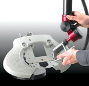
On heavy-duty production lines, a "please do not touch" mentality can occasionally reign. That's where the ROMER CimCore portable Laser Scanning Inspection System comes in.
"Because laser scanning is noncontact, it is particularly well-suited for materials like leather, fabric, foam, thin sheet metal, thin plastic-anything that you can't touch with a hard probe," says Paul Evans, marketing manager for ROMER CimCore. Users can access difficult-to-reach locations on the product, whether inside, topside or underneath.
The laser scanning head, a key component of the system, is used widely on automotive industry production lines for flush-and-gap measurement, says Evans. The heads, or cameras, are designed to be mounted on a production line. "As the car body moves along the line, these cameras, which are built into fixtures around the vehicle, scan the vehicle as it passes in front of them," he says. "It basically looks at all the gaps in the vehicle, such as the gap between a door and the side panel, checking the gap and its consistency between the door and the sheet metal, all around the door."
ROMER took that technology a step further, Evans explains, and the camera manufacturer adapted the device for ROMER's portable arm. ROMER also worked with its software partner to develop a program called Point-Cloud. As the user scans a work piece with the arm and laser scanning head, the system collects 23,000 points a second, permitting a detailed inspection of geometric and surface features of the part against a CAD model.
Those points are imported into the company's PowerINSPECT inspection software. "Once these points are in PowerINSPECT, we can give you a real-time bit map, what we call a weather map-a graphical representation of your part on the computer screen," Evans says. The map is essentially a color gradient graphic that indicates whether the points are in tolerance, above tolerance or below tolerance. "It's basically an instant map of the component's accuracy," he says. "So, hopefully, the majority of the part would be green, meaning it's in tolerance. Blue means you might be under tolerance, and red means you might be over tolerant." In addition, a filter can be used so that only those points that are out of tolerance are displayed on the computer or included in the report.
This, in turn, allows inspectors to tell immediately where the part is good and where the part needs work. "In the past, they would get a statistical report in Excel spreadsheets," Evans says. "But it can be hard to decipher all this information. With our system, a picture is worth a thousand words, and you can just look at it and tell what the story is-in real time."
The data can be used for detailed, off-line analysis and reporting; numerous editing options are available. A file format allows users to combine inspection information with the original CAD data, the sequence of operations and the inspection reports. The system accuracy is ±0.050 millimeter plus arm accuracy.
The camera's placement on the adjustable arm is especially useful because it allows users to scan work pieces that are outside the scope of hard probes, Evans says. He points to vehicle headliners as an example. "It's made of cloth and foam, and you can't really touch it with a hard probe because you'll deform it and be unable to take good measurements." The adjustable arm also allows users to reach otherwise difficult spots such as underneath a car seat. "It gives you versatility for use on different applications," Evans says. The system can also be used for reverse engineering, Evans notes. And its applications extend beyond manufacturing, including graphic arts and architecture.
The system includes a six- or seven-axis 3000i portable coordinate measuring machine (CMM), a scanning probe and a geometric/surface inspection software package. The system can run off either a high-
powered laptop computer or a desktop computer; the complete system includes the computer. A typical configuration includes the ROMER CimCore portable CMM with measuring ranges from 4 to 15 feet, removable ZERO-G counterbalance, laptop computer, 15-meter ball,
6-millimeter ruby ball and point tip probes, laser scanning probe, magnetic base, PowerINSPECT with Point Cloud, WinRDS, and HighRes reverse-engineering software, NIST-traceable calibrated length standard, warranty and carrying case.
TECHNOLOGY CONTACT
For more information on the laser scanning inspection
system, contact:
Romer CimCore Inc.
27240 Haggerty Road, Suite E-20
Farmington Hills, MI 48331
(800) 218-7125
Fax: (248) 324-0525
E-mail: [email protected]
www.romer.com
Quality Specs
QUALITY SPECS1. The laser scanner collects 23,000 points per second.
2. Geometric and surface features can be compared against a CAD model.
3. Data points can be turned into a real-time bit map.
Looking for a reprint of this article?
From high-res PDFs to custom plaques, order your copy today!


