Quality Measurement: Be Precise with Optical Measurement
Many modern manufacturing operations require dimensional or positioning accuracies in the microinch range. Because the components being measured are usually small and delicate, noncontact measuring techniques are often required. In these high-accuracy measurements, two basic types of systems exist: field of view (FOV) and point-to-point (PTP).
The decision to use one type or the other is based on the relationship between the accuracy requirement and the size of the area being measured. If the features are small or close enough together that an image of the entire measurement can be captured within the field of view of a microscope, an FOV system is likely to be the cost-effective choice. An FOV system is commonly used for measuring line widths and other small features on semiconductor wafers.
FOV and PTP systems can be configured to share many design and construction technologies. For example, the techniques developed to produce nanometer-level precision in FOV measurement applications can be applied to improve PTP measurements, while the robust structure designs and vibration control required to perform precise PTP measurements can benefit FOV measurement applications. Among the techniques applied to both measurement types are precise focusing of the image, subpixel image feature detection, smooth and precisely controlled X, Y and Z-motion between measurement points and extreme stability of the system structure to minimize thermal effects and the effects of internal and external vibration sources.
Individual features that contribute to the overall design and performance capabilities for an ideal noncontact measurement system include precision motion control, vibration isolation, a vision system, autofocus control, subpixel feature measurement and programmable software.
Move it precisely
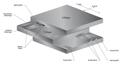
Precision motion control is achieved by many methods including the mechanical design of the X-Y positioning stage and the Z-axis, also referred to as the focusing axis, as well as the materials used to build the system components. With regard to the X-Y stage, an advanced drive mechanism with a pin coupling enables the drive force to be applied solely in the intended direction of travel to ensure accurate positioning. A dual-loop servo system controls the motion of the platform along stress-relieved, hand-lapped, cast iron guideways and positions the cast iron X-Y stage plates with nanometer precision. Stage movement can be done quickly, moving at speeds of several inches per second, to within nanometers of the desired position. Each servomotor uses an incremental rotary encoder to provide information to the servo controller regarding the rotary motion of the motor shaft. In addition, each axis uses a linear encoder mounted to the moving component to relay position information to the servo controller.Linear and rotary encoders are photoelectric devices that scan a grating strip to determine the relay position information. The servo controller controls the position of the moving axis by monitoring the position data from the motor shaft and from the linear moving table. The servo control board assimilates the position information from both sources and commands the motor drive amplifier according to the difference between where the drive axis is and where it should be at any given time.
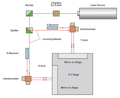
The linear and rotary encoders used in the positioning systems provide precision and repeatability. For more precise positioning and measurement accuracy, systems can be equipped with laser interferometers. Laser interferometry, based on coherence, uses a laser beam emitted at a single frequency or a pair of frequencies. In its simplest configuration, interferometry is the measurement of frequency differences between transmitted and received laser light. Thus a change in position, such as the movement of a table in the X direction, causes a measurable difference in the frequency between a light beam reflected from the moving component and one reflected from a stationary reflector. For multiaxis positioning, one or more beamsplitters split the laser light in to beams measure travel in the X and Y directions.
Movement along the Z-axis during focusing of the optic system is controlled by the dual-loop servo system, with position information being relayed either by a linear actuator or a laser interferometer. The Z-axis can incorporate either a proprietary flexure mechanism or an air bearing. The flexure mechanism can be placed at any height, as much as 4 inches above the stage surface. It uses a parallelogram flexure motion that allows the optical focus point to be positioned within a vertical travel of 0.1 inch.
For longer travel in the Z-axis, counterbalanced air bearings can be used. The air bearings, which require pressurized clean and dry air, include a stainless steel box with porous media that rides along a granite bar. Granite eliminates the potential of damage in case of a loss of air supply.
No shaking
Measurement accuracy of FOV and PTP measurement systems can be adversely affected by vibration and shock from external and internal sources. Vibration can result from other operating equipment located on the production floor, or moving components within the measuring system itself. X-Y travel of the platform, in particular the acceleration and deceleration of the massive stage, is an example of internal vibration. This motion can create forces that must be prevented from degrading measurement accuracy.Vibration is a dynamic force that results in a sine wave-type of motion that continues until the force is no longer applied and the deflection amplitude decreases to where the moving mass comes to rest. Vibration causes an adverse impact on precision dimensional measurements because of the positional relationship between the X-Y stage, which in most cases carries the part being measured, and the Z-axis that carries the imaging optics. Under vibration, the relative positions of the X-Y stage and Z-axis are unpredictable, and accurate measurements are impossible.
The most effective way to negate vibration is with a vibration isolation table. These tables are equipped with a rigid welded-metal frame and heavy granite base. The base is isolated from the table frame with either air-filled rubber supports or active antivibration supports, in which the internal pressure is regulated to provide only enough upward force to lift the measuring components.
In addition to the steps taken to build in vibration isolation, the ideal noncontact measurement system must minimize internal vibration. DC servomotors are used because of their smoother movement. Vibration is also minimized by following an "S-curve" acceleration and deceleration along all axes. An "S-curve" motion profile has acceleration and deceleration increasing and decreasing slowly, to avoid sudden jolts that could induce vibration in the measuring components.
The ‘vision'
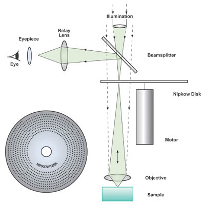
The vision system uses a microscope optical system with a charged-coupled device (CCD) camera, frame grabber board and image analysis software. The microscope magnifies the image so that the size or location of the features can be precisely measured. Multiple objective lenses can be used, depending on the requirement, with an automatic objective lens changer. A vertical illuminator provides incident illumination to the part being measured, either from the top or from the bottom.A computer-controlled light source provides illumination to a fiber optic bundle that conducts the light to the vertical illuminator or to a condenser lens for transmitted illumination. The light passes through a field diaphragm that defines the size of the illuminated area on the part being measured, and an aperture diaphragm, which adjusts the angle of the cone of light provided to the object. The aperture diaphragm affects the image brightness, image resolution and image contrast.
After passing through the aperture diaphragm, the light is reflected downward by a beam splitter, and passes through the objective lens to the part being measured, but only in the case of reflected illumination. The light reflected from, or transmitted through, the measured part passes up through the objective lens and through the beam splitter to a photographic eyepiece at the top of the camera adapter. The eyepiece focuses the image on the CCD array of the video camera.
The camera transforms the image into a signal that is delivered to the frame grabber board. That image then becomes digitally stored in the computer, where resident software analyzes it and transfers the stored image to the computer monitor.
A confocal microscope can also be used. The confocal microscope produces a single plane of focus-a single horizontal slice of the part being measured-that results in accurate focus detection for 3-D measurements.
Bring it in focus
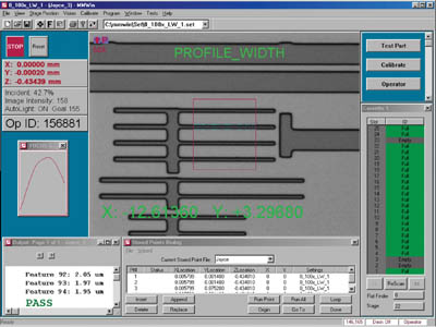
The correct focus is a critical factor in measurement repeatability. An autofocus function scans a small distance along the focus axis, toward and away from the part. The image sharpness is analyzed at many points during the scan and the maximum point of sharpness is calculated from the collected data. The objective lens is then moved to the optimum focus point for measurement. If the function is enabled, it will be performed each time a measurement is performed.A state-of-the-art noncontact measurement system can do coordinate and critical dimension measurements with feature sizes as small as 0.25 micron, depending on the particular system. Linewidths from 0.5 to 40 microns can be measured, with 1 Sigma repeatability, to as small as 1.5 nanometer or better.
For both FOV and PTP systems, determining edge location is an essential step. Practically speaking, the edges of lines in an image occur where the image brightness and intensity changes from light to dark or from dark to light. The transition usually occurs across several pixels because of the high system magnification, and the manufacturer must select a threshold value for defining the exact location of the edge. The FOV or PTP system can then analyze pixels in a direction perpendicular to the edge to determine at which location in the pixel grid, the image intensity exactly equals this value. The precise edge locations are determined for each scan line within the measurement window, even though the edges will most likely occur between pixels. By image averaging, interpolation and statistical processing, the subpixel location of the edge can be reliably determined, making it possible to repeatably measure edge locations to approximately 1% of a pixel.
It's in the software
Each application of the FOV or PTP system requires that it perform some set of measurements, and then analyze or simply report the results of the measurements. In many cases, automated operation is desired. The noncontact measurement system has prewritten measurement programs for typical jobs. In addition, powerful custom measurement and analysis routines should be easily created to meet individual requirements. While all measurement functions can be controlled manually, software allows the execution of preprogrammed measurement sequences, combining multiple measurements with analysis to determine actions based on results of previous measurement. Such programs can include moving of positioning axes, measurement calculations, edge detection, pattern recognition with subpixel accuracy, setting controls such as autofocus and automatic illumination, and analyzing measurement data for output and reporting purposes.When precision is needed
When manufacturing operations specify dimensional measurement or positioning accuracies in the single nanometers, such precision can be achieved only with a noncontact FOV or PTP system that uses certain critical features. Advanced motion control with a drive mechanism ensures the drive force is applied strictly in the intended direction of travel, a dual-loop servo system and linear encoders. One also needs to isolate vibration and shock through the table and platform to prevent such effects from degrading accuracy.Also essential are proprietary sub-pixel feature detection software, a vision system that combines the advantages of a high-magnification microscope with a CCD camera and precise focus control.
By understanding all these factors, and ensuring their presence on any system, manufacturers can make the decision on whether to invest in an FOV or PTP system that would best fit their applications.
TECH TIPS
• Noncontact measurement of coordinates and critical dimensions in the manufacture of high-precision parts, assemblies and electronic circuits mandates strict parameters such as subpixel vision measurement, precision motion control, magnification optics, vibration control and structure robustness.• An ideal system optimizing such features enables 1-D, 2-D and
3-D measurements with an accuracy of 0.01 µm and repeatability of ± 0.002 µm.
Looking for a reprint of this article?
From high-res PDFs to custom plaques, order your copy today!


