Quality 101: Calibration of Machine Tools: Why, What and How
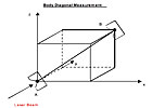
This schematic shows a total of four Body Diagonal measurement directions. Source: Optodyne Inc.
In the past, calibration and compensation have been considered strictly quality issues. Today, adopters acknowledge that calibration and compensation directly relate to substantial improvement in throughput because feed rates can be set higher when machines are known to be in tolerance. As a result, calibration and compensation of computer numerical control (CNC) machine tools is becoming routine, particularly in shops producing parts for the aerospace and medical industries.
And when machines are in tolerance, parts are produced with higher accuracy, which dramatically cuts downstream costs such as assembly, warranty and in-field service. Furthermore, calibration and compensation provide an early warning system for detecting and predicting when the positioning of a machine tool is likely to need repairs. This minimizes interruptions of sometimes critical production runs for maintenance operations.
The Body Diagonal Measurement Method, described in the ASME B5.54 and ISO 230-6, provides a quick check of 3-D volumetric accuracy. Source: Optodyne Inc.
21 Rigid Body Errors
Many theories have been proposed for measuring accuracy, from simple measurement of linear/displacement error to non-rigid body errors based on Taylor’s Linear Expansion Theory, which requires 45 measurements to determine errors. However, the most widely accepted theory, the Rigid Body Theory, used for measuring 3-D volumetric machine tool accuracy, falls between the two extremes. The Rigid Body Theory suggests 21 errors, including three linear/displacement, three vertical straightness, three horizontal straightness, three roll angular, three pitch angular, three yaw angular and three squareness.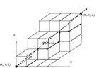
Shown here is Trajectory of Sequential Step Diagonal displacement measurement in the PPP diagonal direction. The measurement direction and the machine movement directions are not parallel. Hence, a flat-mirror target is needed to reflect the laser beam to the laser head. Source: Optodyne Inc.
Linear Calibration
The use of linear/displacement calibration assumes that the largest errors are lead screw pitch error. Basically, the operator aligns a laser calibration system beam parallel to the axis. The system is programmed to record measurements at specified increments along a single axis. When the incremental positioning and data capture begins, the calibration system automatically moves to each specified position and records each measurement. The calibration system compares deviations from each position.For thermal expansion the system generates a compensation table based on a single linear correction factor, except when non-uniform errors occur in specific sections along the axis; in this case, the system must utilize incremental pitch correction factors.
Many years ago, the ASME and ISO recognized that the Linear/Displacement Measurement Method was insufficient to ensure 3-D volumetric accuracy. Linear/Displacement measurement does not consider the relationships between the axes-for example, squareness and straightness measurements, crucial for 3-D accuracy. This led to the ASME B5.54 and ISO 230-6 machine tool body diagonal displacement measurement standards.
The Sequential Step Diagonal Measurement Method provides a cost-effective solution for measuring and compensating 3-D volumetric accuracy. Source: Optodyne Inc.
3-D Volumetric Positioning Calibration
The Body Diagonal Displacement Measurement Method defined by the ASME and ISO standards has provided a quick check of volumetric error with good results for many years. The measurements are relatively easy and quick, minimizing machine downtime and cost.A diagonal is defined by starting at one corner of a base plane and moving to the opposite corner at the top plane. A positive or negative axis movement defines the body diagonal movements. When the directions are reversed, the last four body diagonals use the same corners as the first four body diagonals. As a result, the four body diagonals directions have both forward and reverse movement with only four setups.
The Body Diagonal method only collects four sets of data and nine errors; it does not generate enough information to determine the source and cause of errors. This led to the development of the Sequential Step Diagonal Measurement Method. Here all three axes move in sequence along a body diagonal and collect data after the move of each axis. The laser beam direction (measurement direction) does not run parallel to the motion of the linear axis. Consequently, the method measures errors both parallel and perpendicular to the direction of the linear axis. By collecting data with a laser beam pointing in four body diagonal directions, the Sequential Step method collects 12 types of error data.
The Sequential Step method differs from the Body Diagonal method by moving each axis separately and in sequence; and after each separate movement of the X-, Y- and Z-axis, diagonal positioning error is collected. The Sequential Step method measures along four edges and averages the measurements, resulting in the displacement error through the center of the volume, and higher accuracy.
For example, Abbe offsets, pitch, yaw and roll angular errors affect all the measurements, including linear displacement. Therefore, the linear displacement errors along the X-axis differ when measured at different Y-locations and Z-locations. Accordingly, B5.54 requires linear displacement measurements along three orthogonal lines (parallel to the three axes, passing through the center of the working volume).
The Sequential Step method measures positioning errors caused by angular errors and expresses them as the averaged straightness errors along the centerlines of the working volume. Because most machine tools cannot compensate for angular errors, the averaged straightness errors provide compensation. Note that displacement errors and straightness errors measured along one edge of the working volume will differ from those measured along another edge due to the Abbe offset and angular errors.
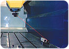
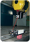
Laser vector measurement on a five-axis linear motor machine. The laser head is on the bed and the flat-mirror is on the spindle. The measurement volume is 3,000 millimeters in X, 2,000 millimeters in Y and 1,000 millimeters in Z. Source: Optodyne Inc.
Measurement of Thermal Expansion
One of the most significant factors influencing the accuracy of a final part is the thermal behavior of a machine tool. The absence of a routine appropriate for measuring volumetric accuracy in relation to thermal behavior has hindered thermal compensation.For determining machine tool accuracy in thermally unbalanced conditions, the Sequential Step method provides a viable process when thermal compensation of linear/displacement errors aggravates straightness and squareness errors. Because of the short measurement time, the Sequential Step method can be used to measure the 3-D positioning errors in a thermal state caused by the machine temperature changes due to such factors as the environment, motion, speed, cutting force and coolant.
In the meantime, a set of thermocouples placed at key locations on the machine tool structure can measure the machine temperature. The measured data can be used to model the relationship between temperature distribution and the 3-D positioning errors. Additionally, the data can be used to generate compensation tables for various thermal conditions to ensure positioning accuracy.
The Linear/Displacement Measurement Method, while able to measure errors along a single axis, does not consider the straightness, squareness and perpendicularity of the axes to each other. Therefore, it does not provide an accurate compensation method for the 3-D parts designed on today’s 3-D CAD/CAM systems.
The Sequential Step Diagonal Measurement Method provides a more comprehensive process for assessing 3-D volumetric machine tool accuracy. With the capability of examining thermal 3-D volumetric behavior, the Sequential Step Method provides a solution that ensures maximum machine tool performance and productivity.
Looking for a reprint of this article?
From high-res PDFs to custom plaques, order your copy today!


