The Automation Renovation
Follow these guidelines to successfully add your first vision system.
A renovation always looks easy on paper. Just pry off that wood paneling and prime the existing drywall. It won’t take long at all. But after that 1970s rec room wood paneling comes off to reveal the drywall crumbling away, the homeowner has hit an unexpected snag. Even if they are the DIY type, they still have to buy new drywall, fit it into the car, take it home and install it. The project gets put on hold, and they have lost time because of an unexpected setback.
Building a vision system is a lot like renovating a house, especially for those upgrading an existing manufacturing system to include vision. There are dozens of details to consider and a lot of hard work. Even the best-planned project can hit a snag. For those who are not architects or contractors, they could be building for a long time.
Experts in the machine vision field say that vision is often an afterthought in manufacturing systems. Adding vision is often thought of as an upgrade, so like a home renovation, operators will have to work within the limitations of their current space.
Any upgrades to a house should have some kind of project plan with blueprints, specifications and dimensions, as well as a plan B tucked away in case of unforeseen events. When planning a vision system, determine requirements, research equipment and look into industry regulations.
One way to determine requirements is to develop the project in three stages.
First, brainstorm a list of tasks for the vision system to accomplish. In this sketchbook stage, operators will answer some basic questions.
Next, determine the equipment needed to work on the prototype in the lab or at the test bench. Use a camera to take sample images.
Finally, look at how the vision system fits into the production process and choose the equipment. After building a working prototype, move it to the factory floor to see how it fits.
Determine the vision system’s expected performance in terms of its accuracy, precision and repeatability. In metrological terms, accuracy is defined as the degree to which a given measurement conforms to the standard value for that measurement. Indeed, governments oversee weights and measures to ensure instruments give accurate results. Precision defines the degree of certainty with which a measurement can be stated. Repeatability is the range of variation in repeated measure-ments. If an object is measured 10 times by different people and they get the same result, one can assume that the measurement process is highly repeatable.
But in a vision system, it is the image of the object that gets measured. The imaging software will use the pixels-mapped to the real-world coordinate system through calibration-to calculate the measurements of the object. An important rule of metrology is that the instrument should be 10 times better than what operators want to measure. If the object has a tolerance of ± 0.5 millimeter, then the image’s pixels must be in the order of 50 microns. Essentially, the relationship between the camera and working plane will influence the optics. And most-if not all-image processing packages offer sub-pixel accuracy, so operators will be sure to get the required precision from their images, if they have the right lens.
The application’s expected speed is another factor to consider in stage one. Operators need to know the rate their widgets will pass the camera’s field of view. With the timings, they will figure out how much time is available for processing, and the camera vendor and later the software ven-dor will be able to understand the application’s needs.
Next, the camera and lighting must be considered. Where will they go? Operators will have to determine the physical constraints and environment of the system, making sure that the camera will fit in the space available. Lighting is another consideration.
The factory environment is important here too. The environmental variables are temperature, humidity, dust, vibrations and electromagnetic noise from DC motors. If the camera’s wire or cable is placed near a DC motor or its housing, the motor’s electromagnetic noise could corrupt not only the transmission, but the image data as well.
If the system is to be PC-based, determine the proximity of the camera to the computer. The cable length will determine the choices for the camera interface. This is true even for a smart camera because the cables have to connect to something. Operators also will want to take cable flexing into account if the cable is part of a moving assembly.
How will the vision system be operated? Will it be deeply embedded or will it have a user interface? If the latter needs to be considered, determine the requirements for the human-machine interface (HMI). Some industries have very strict controls and require product tracking at every step in the manufacturing process. The pharmaceutical industry, for example, requires access permissions and change logs for regulatory compliance.
The last step in the sketchbook phase is straightforward math. It is time to come up with a budget. Estimate both upfront and recurring costs, and do not forget maintenance costs such as cleaning, lighting replacements and regulatory compliance updates.
In order to develop the application’s software, operators need to have a clear idea of what the software will “see” in the images. So take pictures-lots of them. Operators will need a representative set of images that show the range of situations (defects) that could occur. This set of images will show how the scene or object can change over time. Take pictures of good and as many atypical images as possible; remember, it is the defects one wants the vision system to find. If, for example, the system is inspecting machined parts, be sure to acquire images of burrs, parts that are bent or parts with too-small openings.
Look at the images carefully. Take note of shadows (dark regions), reflections (bright spots) or uneven lighting. The human visual system is fine tuned to spot irregularities in images, but a computer is not. For example, if the software is looking for edges, an object’s shadow might be misinterpreted as an edge. A reflection could be counted as a blob. A picture is only as good as its lighting, and depending on what appears in the images, operators may need to tune or reconsider the illumination setup.
Imaging algorithms used in machine vision applications generally fall into three categories. The first group of tools is used for locating. Locating tools go by names such as pattern recognition, pattern matching, pattern search algorithms and blob analysis. They are good examples of the superiority of the human brain; humans can easily see the object in an image, but a computer needs a little help. A locating algorithm determines the coordinates of an object so that other analysis functions have a reference point. Locating algorithms also help speed up the processing for other measuring and reading functions by closing in on an area of interest.
The next group of algorithms is used for measuring. These tools go by names such as measurement, metrology, edge-and-stripe and blob analysis-some tools have multiple uses. Measurement tools are quite capable of measuring geometric features and will allow operators to set tolerances to help sort the conforming parts from the defective ones. These tools are indispensible for many applications, especially for machined parts. If operators are measuring objects and want results in world units, calibration tools also will find their way into the toolbox. Most machine vision applications make use of a calibrated coordinate system.
The third group of algorithms is used for reading. Alphanumeric characters come to mind with the word “read.” Machine vision reads characters for two purposes. The first is for optical character verification (OCV), which determines the presence or absence of specific printed text, such as an expiration date. The second is optical character recognition (OCR), which actually reads the characters and returns them as results. In machine vision, reading also can refer to 1-D and 2-D codes, or more specifically, both bar and matrix codes.
Machine vision specialists recommend using off-the-shelf tools instead of creating algorithms from scratch. Several image-processing packages are available, and the well-known ones are built with field-proven technology. Consider that developing and maintaining algorithms is extremely time-consuming and expensive. A vendor might have a large team of highly skilled and experienced developers working on image processing algorithms. If operators choose to buy instead of build, they will spend their time developing the application and not creating algorithms. Remember too that a particular vision problem typically has more than one solution, and an image-processing package will provide many options. Frankly, the algorithm, or more likely algorithms, used in the solution must be designed to catch the anomalies.
Now consider the vision system’s role in the manufacturing system, or possibly the entire enterprise. Think about what will be done with the imaging results and how the vision system must interact with other equipment. What must happen to a part that fails inspection? Will the system blast it with an air jet? Instruct a robot gripper to pick the object off the line? These are mechanical issues that will shape the physical design of the system. On the back end, what will happen to the results gathered from the vision system? Will they be used to make real-time decisions, for example, to activate an ejector? Do operators need to keep statistics in order to identify trends? Do they need to archive the images for regulatory compliance? When they are at the point of answering these questions, they are well on the way to building a prototype; the system validation must be done in-process and not just in the lab.
It might even be necessary to take a few steps backward and revisit the camera setup. The camera, optics, lighting and algorithm selection process is iterative; operators might find the chosen algorithm does not work properly in the setup. For example, 2-D code reading will work best if the minimum element size is 3 pixels tall and wide, so the camera setup needs to resolve to this level.
At the same time, implementing vision is not a decision to be taken lightly, and the DIY approach requires expertise and time. Are you prepared for the work that is involved? If not, consult a systems integrator who specializes in machine vision. These integrators will be able to guide operators through the process. They have the experience and foresight to prevent bad choices. Machine vision’s complexity can be overwhelming, and working with an expert will ensure a successful deployment. V&S
Brainstorm a list of tasks for the vision system to accomplish. This stage will answer some basic questions.
Determine the equipment needed to work on the prototype in the lab or at the test bench. Use a camera to take sample images.
Look at how the vision system fits into the production process and choose the equipment. After building a working prototype, move it to the factory floor to see how it fits.
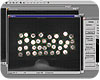
The imaging software will help determine the correct shape, index it so as not to overfill the tray and send coordinate information to the robot. Source: Bosch Packaging Technology
A renovation always looks easy on paper. Just pry off that wood paneling and prime the existing drywall. It won’t take long at all. But after that 1970s rec room wood paneling comes off to reveal the drywall crumbling away, the homeowner has hit an unexpected snag. Even if they are the DIY type, they still have to buy new drywall, fit it into the car, take it home and install it. The project gets put on hold, and they have lost time because of an unexpected setback.
Building a vision system is a lot like renovating a house, especially for those upgrading an existing manufacturing system to include vision. There are dozens of details to consider and a lot of hard work. Even the best-planned project can hit a snag. For those who are not architects or contractors, they could be building for a long time.
Experts in the machine vision field say that vision is often an afterthought in manufacturing systems. Adding vision is often thought of as an upgrade, so like a home renovation, operators will have to work within the limitations of their current space.
Any upgrades to a house should have some kind of project plan with blueprints, specifications and dimensions, as well as a plan B tucked away in case of unforeseen events. When planning a vision system, determine requirements, research equipment and look into industry regulations.
One way to determine requirements is to develop the project in three stages.
First, brainstorm a list of tasks for the vision system to accomplish. In this sketchbook stage, operators will answer some basic questions.
Next, determine the equipment needed to work on the prototype in the lab or at the test bench. Use a camera to take sample images.
Finally, look at how the vision system fits into the production process and choose the equipment. After building a working prototype, move it to the factory floor to see how it fits.
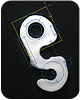
This imaging library module analyzes the image of a machined hook. Based on its features, the metrology results determine that the part falls outside the accepted tolerances. Source: Matrox Imaging
The Sketchbook
Brainstorm. Scribble. Sketch. Whichever word is used, this is the time to establish the parameters and the role of the new vision system. The basic question is: what do you want vision to do? Does the application require it to guide? For example, does it need to pass coordinates to a stage, robot or gantry? Will the system inspect objects? For example, will it count pills in a blister pack or measure the dimensions of machined parts? Or read text characters or 1-D and 2-D barcodes? Many applications will perform several functions, so list everything the vision system is expected to do.Determine the vision system’s expected performance in terms of its accuracy, precision and repeatability. In metrological terms, accuracy is defined as the degree to which a given measurement conforms to the standard value for that measurement. Indeed, governments oversee weights and measures to ensure instruments give accurate results. Precision defines the degree of certainty with which a measurement can be stated. Repeatability is the range of variation in repeated measure-ments. If an object is measured 10 times by different people and they get the same result, one can assume that the measurement process is highly repeatable.
But in a vision system, it is the image of the object that gets measured. The imaging software will use the pixels-mapped to the real-world coordinate system through calibration-to calculate the measurements of the object. An important rule of metrology is that the instrument should be 10 times better than what operators want to measure. If the object has a tolerance of ± 0.5 millimeter, then the image’s pixels must be in the order of 50 microns. Essentially, the relationship between the camera and working plane will influence the optics. And most-if not all-image processing packages offer sub-pixel accuracy, so operators will be sure to get the required precision from their images, if they have the right lens.
The application’s expected speed is another factor to consider in stage one. Operators need to know the rate their widgets will pass the camera’s field of view. With the timings, they will figure out how much time is available for processing, and the camera vendor and later the software ven-dor will be able to understand the application’s needs.
Next, the camera and lighting must be considered. Where will they go? Operators will have to determine the physical constraints and environment of the system, making sure that the camera will fit in the space available. Lighting is another consideration.
The factory environment is important here too. The environmental variables are temperature, humidity, dust, vibrations and electromagnetic noise from DC motors. If the camera’s wire or cable is placed near a DC motor or its housing, the motor’s electromagnetic noise could corrupt not only the transmission, but the image data as well.
If the system is to be PC-based, determine the proximity of the camera to the computer. The cable length will determine the choices for the camera interface. This is true even for a smart camera because the cables have to connect to something. Operators also will want to take cable flexing into account if the cable is part of a moving assembly.
How will the vision system be operated? Will it be deeply embedded or will it have a user interface? If the latter needs to be considered, determine the requirements for the human-machine interface (HMI). Some industries have very strict controls and require product tracking at every step in the manufacturing process. The pharmaceutical industry, for example, requires access permissions and change logs for regulatory compliance.
The last step in the sketchbook phase is straightforward math. It is time to come up with a budget. Estimate both upfront and recurring costs, and do not forget maintenance costs such as cleaning, lighting replacements and regulatory compliance updates.
Set Up the Lab
When operators know the application’s requirements, they can shop around for the components. After they have the smart camera or camera, frame grabber, PC and illumination device, they get to have some fun. It is time for the photo shoot.In order to develop the application’s software, operators need to have a clear idea of what the software will “see” in the images. So take pictures-lots of them. Operators will need a representative set of images that show the range of situations (defects) that could occur. This set of images will show how the scene or object can change over time. Take pictures of good and as many atypical images as possible; remember, it is the defects one wants the vision system to find. If, for example, the system is inspecting machined parts, be sure to acquire images of burrs, parts that are bent or parts with too-small openings.
Look at the images carefully. Take note of shadows (dark regions), reflections (bright spots) or uneven lighting. The human visual system is fine tuned to spot irregularities in images, but a computer is not. For example, if the software is looking for edges, an object’s shadow might be misinterpreted as an edge. A reflection could be counted as a blob. A picture is only as good as its lighting, and depending on what appears in the images, operators may need to tune or reconsider the illumination setup.
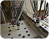
Vision-guided robots are quite common. The camera acquires an image, and software processes the image. In this sorting application, the robots place products into a blister tray for packaging. Source: Bosch Packaging Technology
What Goes Into the Toolbox?
With a complete set of images, operators will be able to analyze them. Requirements can be put into concrete terms to help determine the type of machine vision tools (algorithms) needed.Imaging algorithms used in machine vision applications generally fall into three categories. The first group of tools is used for locating. Locating tools go by names such as pattern recognition, pattern matching, pattern search algorithms and blob analysis. They are good examples of the superiority of the human brain; humans can easily see the object in an image, but a computer needs a little help. A locating algorithm determines the coordinates of an object so that other analysis functions have a reference point. Locating algorithms also help speed up the processing for other measuring and reading functions by closing in on an area of interest.
The next group of algorithms is used for measuring. These tools go by names such as measurement, metrology, edge-and-stripe and blob analysis-some tools have multiple uses. Measurement tools are quite capable of measuring geometric features and will allow operators to set tolerances to help sort the conforming parts from the defective ones. These tools are indispensible for many applications, especially for machined parts. If operators are measuring objects and want results in world units, calibration tools also will find their way into the toolbox. Most machine vision applications make use of a calibrated coordinate system.
The third group of algorithms is used for reading. Alphanumeric characters come to mind with the word “read.” Machine vision reads characters for two purposes. The first is for optical character verification (OCV), which determines the presence or absence of specific printed text, such as an expiration date. The second is optical character recognition (OCR), which actually reads the characters and returns them as results. In machine vision, reading also can refer to 1-D and 2-D codes, or more specifically, both bar and matrix codes.
Machine vision specialists recommend using off-the-shelf tools instead of creating algorithms from scratch. Several image-processing packages are available, and the well-known ones are built with field-proven technology. Consider that developing and maintaining algorithms is extremely time-consuming and expensive. A vendor might have a large team of highly skilled and experienced developers working on image processing algorithms. If operators choose to buy instead of build, they will spend their time developing the application and not creating algorithms. Remember too that a particular vision problem typically has more than one solution, and an image-processing package will provide many options. Frankly, the algorithm, or more likely algorithms, used in the solution must be designed to catch the anomalies.
Moving to the Factory Floor
The big picture stage is when operators begin building the machine. They have done all the prep work and assembled the materials. It is time for serious building. Do not take out the power tools just yet, though. A vision system is more than Legos that can be broken apart to make space for a new piece.Now consider the vision system’s role in the manufacturing system, or possibly the entire enterprise. Think about what will be done with the imaging results and how the vision system must interact with other equipment. What must happen to a part that fails inspection? Will the system blast it with an air jet? Instruct a robot gripper to pick the object off the line? These are mechanical issues that will shape the physical design of the system. On the back end, what will happen to the results gathered from the vision system? Will they be used to make real-time decisions, for example, to activate an ejector? Do operators need to keep statistics in order to identify trends? Do they need to archive the images for regulatory compliance? When they are at the point of answering these questions, they are well on the way to building a prototype; the system validation must be done in-process and not just in the lab.
It might even be necessary to take a few steps backward and revisit the camera setup. The camera, optics, lighting and algorithm selection process is iterative; operators might find the chosen algorithm does not work properly in the setup. For example, 2-D code reading will work best if the minimum element size is 3 pixels tall and wide, so the camera setup needs to resolve to this level.
Is there a Stage 4?
Performing automated inspection with machine vision techniques is widely accepted across myriad industries. It has great potential to reduce long-term costs and improve quality control of products. That is key here, because vision is not meant to-and will not-fix your product. Instead, its purpose is to ensure the product’s quality. Over time, it might even help define flaws in the manufacturing process.At the same time, implementing vision is not a decision to be taken lightly, and the DIY approach requires expertise and time. Are you prepared for the work that is involved? If not, consult a systems integrator who specializes in machine vision. These integrators will be able to guide operators through the process. They have the experience and foresight to prevent bad choices. Machine vision’s complexity can be overwhelming, and working with an expert will ensure a successful deployment. V&S
Tech Tips
One way to determine requirements is to develop the project in three stages.Looking for a reprint of this article?
From high-res PDFs to custom plaques, order your copy today!


