Improve Productivity with Hardness Testing
Indentation hardness, traditionally reserved for the lab, has evolved to in-situ production applications to improve yields, reduce costs, maximize resources and generally improve the overall productivity of an operation.
The meaning of material hardness depends on what and how a material is measured or analyzed.
Indentation hardness is arguably the most recognized type of testing when the term hardness is used, and certainly when associated with metals. Common applications of indentation hardness include assessing a metal or plastic material’s elastic properties based on a penetration depth, determining a material’s quality after heat treating or other metal preparation processes, validating a material’s integrity such as the coalescence quality of welds and overlays, and a general quality determination of a material’s tolerance to wearing based on physical and environmental conditions.
Indentation hardness, which traditionally has been reserved for the laboratory, has evolved to in-situ production applications where the strategy is to integrate on-line testing and analysis within the work cell to improve yields, reduce costs, maximize resources and generally improve the overall productivity of an operation. The goal is to produce, test and make a product more readily available to its intended market as quickly as possible without compromising quality.

There are a number of recognized and commonly used indentation hardness methods, each having their individual characteristics and attributes for determining resistance to permanent or plastic deformation. The method used is generally chosen because “we’ve always done it this way” as opposed to “this way is better than that way.”
Evolving standards such as ASTM E18 for Rockwell testing attempts to define industry-accepted hardness specifications. ASTM E18 outlines the proper parameters for each of the measurable components of the test, specifically those verified in a direct verification. The document does not specify the method of loading. As a matter of fact, none of the loading methods-dead weight, spring or load cell-are even mentioned in the specification. Currently, the National Institute of Standards and Technology (NIST) only offers standard reference materials (SRM) for the Rockwell C-scale.
SRM test blocks are used by hardness test block manufacturers to calibrate the instruments that they use to calibrate hardness blocks. The goal is to ensure that the block manufacturer’s standardizing machine produces results as close as possible to the NIST standardizing machine. All test-block manufacturers claiming NIST traceability must, among other things, use NIST-traceable blocks to calibrate their standardizing machines.
Because NIST only offers SRM blocks for the HRC scale, only Rockwell C-scale blocks can be commercially produced with NIST traceability. Therefore, only the HRC scale can be calibrated traceable to NIST. All other scales are calibrated in conformance with ASTM E18, while traceability resides with the block manufacturer.
Also referred to as the diamond-pyramid hardness test, the Vickers indentation hardness test uses a square-based diamond indenter. The diamond angle is comprised of four faces each cut at a 136-degree angle. This configuration was developed because it approximates the most desirable ratio of indentation diameter to ball indenters used in the Brinell method. The Vickers hardness number (VHN or VPH) is defined as the applied force divided by the surface area of the indentation. The Vickers method is useful on materials with a small surface area on which to test since the indentation and area created by the indentation are microscopic.
The Knoop indentation test is used for very thin materials or materials that are characteristically brittle. This test method was developed in 1939 by Frederick Knoop, and is considered a micro hardness testing method. Like the Vickers method, the Knoop method also employs a pyramidal diamond indenter. Surface preparation is of paramount importance on this type of test where the surface to be tested is highly polished. The diamond is pressed onto the polished surface at a known force for a prescribed dwell time. The resulting indentation is measured optically.
The Rockwell indentation hardness test, developed by Hugh and Stanley Rockwell in 1919, is perhaps the most recognized and widely used. This method is characterized as a differential depth method. It uses the depth of the indentation as a measurement of hardness. A diamond or ball indenter is used. A 10 kgf minor or preload is applied to the material initially seating the sample and helping to minimize the need for surface preparation. The major load is then applied and the difference in depth between the material deformation at the minor load compared to the major load is measured.

Early improvements included basic fixtures for Rockwell testing to hold parts securely so that an operator could achieve more consistent measurements. Part movement during measurement is a leading cause of inaccurate measurement. Custom fixtures for parts, such as automotive engine valves, bearing components and transmission parts had the advantage of securely locating the part and speeding the measurement process.
The development of direct reading Brinell testers yielded automated Brinell measurement systems. The traditional method of using a Brinell tester to make the impression on the part and then reading it with a scope is replaced with an automated system that measures the depth of penetration using Brinell loads and indenters. This eliminates operator influence on the measurement.
These automated Brinell testers lend themselves to automated cells. The systems range from operator loaded testers to fully automated robot loaded systems that sample parts as they are unloaded from an aging furnace. They can work in a dirty, noisy environment, taking accurate readings with no concern of operator error or fatigue.
 Traditional micro hardness testing is a lengthy, time-consuming process. There are two ways to shorten the measurement process. The first is to automate the traditional optical micro hardness with a camera and software to facilitate the measurement of the impressions. From there it is possible to add motorized tables to allow complete automation of the measuring process. This is particularly useful for the measurement of case depth on samples. The basic process is to place the sample in the micro hardness tester. Then the operator uses the software to locate the edge of the part and the direction of the measurement. The software then directs the system to make impressions at predetermined locations, and the system repeats the movements and automatically measures all the impressions. This type of system not only eliminates the operator error inherent in having the operator manually measure the impressions, but allows them to perform other functions while the tester is running.
The second way to decrease case depth measurement time is by using a fully automated system that uses the Rockwell process but with loads in the traditional micro hardness testing range. This system takes measurements much faster than traditional methods and because the tester does not read the impressions optically, part preparation is much less critical, and therefore, much quicker.
Case depth analysis can be looked at as an automatic hardness test. Case depth analysis is a critical measurement on heat-treated parts, such as gears. When heat-treated parts are heated improperly, they may become brittle or too soft, thus prone to failure. Automatic micro hardness testers, complete with a camera, motorized X-Y table and software, can be used for automatic rapid case depth analysis. A traverse, or a series of programmed indentation locations, can be created using software allowing the case depth test to be performed in an automatic mode. Complex traverse profiles with up to 24 individual traverses with each traverse having as many as 50 individual test points can be created. The tester will apply the indentation along the traverse and sequence to measure the indentations and their related hardness reading, typically using a Rockwell C-scale. Preset tolerances can be configured as part of the program to quickly identify nonconforming parts so that modifications to the heating process can be made.

Progressive organizations are using programmable controllers to sequence their manufacturing processes very distinctly, including the process that performs hardness evaluations on product directly from the heat-treating process.
The result of this in-situ hardness testing is providing statistical process control data back to various components within the production loop. Hardness data collected and fed back into the production system is being used to adjust heating parameters, dwell times, annealing and cooling parameters. Specialized fixtures are designed as part of the hardness tester and the integration of the various components used in the manufacturing cell are carefully considered as part of the overall production process.
Hardness testing will continue to play an important role in qualifying products, materials and processes. The method will continue to be performed in laboratories and, in more progressive organizations, on the production floor perhaps as part of a lean manufacturing initiative or deployment. Changes in manufacturing strategies, demands for faster throughput and yields, and optimization of resources and materials are expanding testing that historically had been performed in the lab to the manufacturing cell. NDT
The meaning of material hardness depends on what and how a material is measured or analyzed.
Indentation hardness is arguably the most recognized type of testing when the term hardness is used, and certainly when associated with metals. Common applications of indentation hardness include assessing a metal or plastic material’s elastic properties based on a penetration depth, determining a material’s quality after heat treating or other metal preparation processes, validating a material’s integrity such as the coalescence quality of welds and overlays, and a general quality determination of a material’s tolerance to wearing based on physical and environmental conditions.
Indentation hardness, which traditionally has been reserved for the laboratory, has evolved to in-situ production applications where the strategy is to integrate on-line testing and analysis within the work cell to improve yields, reduce costs, maximize resources and generally improve the overall productivity of an operation. The goal is to produce, test and make a product more readily available to its intended market as quickly as possible without compromising quality.
The advent of new technology has helped to reduce the need for highly polished surfaces prior to taking a hardness measurement. Source: Ametek Inc.
Hardness Methods
It is accepted that indentation hardness is a measurement of a material’s resistance to permanent or plastic deformation when penetrated by another harder material at a specified load for a specified period of time. But different methods for testing indentation hardness and different processes used to apply loads and measure indentations exist.There are a number of recognized and commonly used indentation hardness methods, each having their individual characteristics and attributes for determining resistance to permanent or plastic deformation. The method used is generally chosen because “we’ve always done it this way” as opposed to “this way is better than that way.”
Evolving standards such as ASTM E18 for Rockwell testing attempts to define industry-accepted hardness specifications. ASTM E18 outlines the proper parameters for each of the measurable components of the test, specifically those verified in a direct verification. The document does not specify the method of loading. As a matter of fact, none of the loading methods-dead weight, spring or load cell-are even mentioned in the specification. Currently, the National Institute of Standards and Technology (NIST) only offers standard reference materials (SRM) for the Rockwell C-scale.
SRM test blocks are used by hardness test block manufacturers to calibrate the instruments that they use to calibrate hardness blocks. The goal is to ensure that the block manufacturer’s standardizing machine produces results as close as possible to the NIST standardizing machine. All test-block manufacturers claiming NIST traceability must, among other things, use NIST-traceable blocks to calibrate their standardizing machines.
Because NIST only offers SRM blocks for the HRC scale, only Rockwell C-scale blocks can be commercially produced with NIST traceability. Therefore, only the HRC scale can be calibrated traceable to NIST. All other scales are calibrated in conformance with ASTM E18, while traceability resides with the block manufacturer.
Open- and Closed-Loop Testing
Hardness results are not affected by the loading method. The ASTM E18 specification addresses accuracy, consistency and load rate because inconsistencies in these variables can have dramatic effects on the test results. Any loading method that can meet the strict criteria outlined in the specification is appropriate for use. Hardness testers basically use two different methods for applying a known load or force. Open-loop systems employ calibrated dead weights or elastic members in a complex link-lever-pivot configuration. Closed-loop systems employ a load sensor designed to continually and constantly supply the load measurement feedback to the controller so as to control the applied load and the related indenter deflection. The different methods of indentation hardness may be more suitable to certain testing requirements and environments than others and its intended application should be considered carefully.Common Hardness Methods
Brinell, Vickers, Knoop and Rockwell are common hardness methods. J. A. Brinell developed the first widely accepted indentation hardness test in 1900. His test consisted of indenting a metal surface using a 10-millimeter diameter steel ball at a force of 3,000 kilogram-force (kgf). Softer metals use an applied load of as little as 500 kgf. Brinell’s analysis of hardness was based on measuring the diameter of the impression made by the indentation in relation to the load that was applied. The Brinell hardness number, or BHN, is determined by calculating the load applied divided by the surface area of the indentation, measured optically using a low-powered microscope.Also referred to as the diamond-pyramid hardness test, the Vickers indentation hardness test uses a square-based diamond indenter. The diamond angle is comprised of four faces each cut at a 136-degree angle. This configuration was developed because it approximates the most desirable ratio of indentation diameter to ball indenters used in the Brinell method. The Vickers hardness number (VHN or VPH) is defined as the applied force divided by the surface area of the indentation. The Vickers method is useful on materials with a small surface area on which to test since the indentation and area created by the indentation are microscopic.
The Knoop indentation test is used for very thin materials or materials that are characteristically brittle. This test method was developed in 1939 by Frederick Knoop, and is considered a micro hardness testing method. Like the Vickers method, the Knoop method also employs a pyramidal diamond indenter. Surface preparation is of paramount importance on this type of test where the surface to be tested is highly polished. The diamond is pressed onto the polished surface at a known force for a prescribed dwell time. The resulting indentation is measured optically.
The Rockwell indentation hardness test, developed by Hugh and Stanley Rockwell in 1919, is perhaps the most recognized and widely used. This method is characterized as a differential depth method. It uses the depth of the indentation as a measurement of hardness. A diamond or ball indenter is used. A 10 kgf minor or preload is applied to the material initially seating the sample and helping to minimize the need for surface preparation. The major load is then applied and the difference in depth between the material deformation at the minor load compared to the major load is measured.
New systems are able to decrease measurement time in case depth measurement applications. Source: Ametek Inc.
Automatic Testing
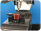
As operators looked for ways to improve production efficiency, speed, accuracy and reduce operator influence, specialized fixtures and innovative techniques became incorporated into the operator’s overall production strategy.Early improvements included basic fixtures for Rockwell testing to hold parts securely so that an operator could achieve more consistent measurements. Part movement during measurement is a leading cause of inaccurate measurement. Custom fixtures for parts, such as automotive engine valves, bearing components and transmission parts had the advantage of securely locating the part and speeding the measurement process.
The development of direct reading Brinell testers yielded automated Brinell measurement systems. The traditional method of using a Brinell tester to make the impression on the part and then reading it with a scope is replaced with an automated system that measures the depth of penetration using Brinell loads and indenters. This eliminates operator influence on the measurement.
These automated Brinell testers lend themselves to automated cells. The systems range from operator loaded testers to fully automated robot loaded systems that sample parts as they are unloaded from an aging furnace. They can work in a dirty, noisy environment, taking accurate readings with no concern of operator error or fatigue.
A number of fixtures and custom testers are available to speed up the testing process, reduce operator influence and increase accuracy and repeatability. Source: Ametek Inc.
The second way to decrease case depth measurement time is by using a fully automated system that uses the Rockwell process but with loads in the traditional micro hardness testing range. This system takes measurements much faster than traditional methods and because the tester does not read the impressions optically, part preparation is much less critical, and therefore, much quicker.
Case depth analysis can be looked at as an automatic hardness test. Case depth analysis is a critical measurement on heat-treated parts, such as gears. When heat-treated parts are heated improperly, they may become brittle or too soft, thus prone to failure. Automatic micro hardness testers, complete with a camera, motorized X-Y table and software, can be used for automatic rapid case depth analysis. A traverse, or a series of programmed indentation locations, can be created using software allowing the case depth test to be performed in an automatic mode. Complex traverse profiles with up to 24 individual traverses with each traverse having as many as 50 individual test points can be created. The tester will apply the indentation along the traverse and sequence to measure the indentations and their related hardness reading, typically using a Rockwell C-scale. Preset tolerances can be configured as part of the program to quickly identify nonconforming parts so that modifications to the heating process can be made.
Traditional micro hardness testing is a lengthy, time-consuming process, but it can be shortened by replacing the traditional optical micro hardness tester with a camera and software to facilitate the measurement of the impressions. Source: Ametek Inc.
Automated Testing
Hardness testing has traditionally been restricted to the quality laboratory or the R&D department. Samples of a material would be tested, evaluated, reported, and then a determination would be made on the material’s suitability for production. However, as with many types of tests that used to be restricted to the lab, hardness testing is becoming more integrated into the production process. Hardness evaluations are being performed directly on the production line so that determinations can be quickly performed and evaluated and necessary changes incorporated more immediately into the production process. In-situ hardness testing improves production efficiency, decreases waste, optimizes resources and can significantly reduce the cycle time to previous batch-based processes.Progressive organizations are using programmable controllers to sequence their manufacturing processes very distinctly, including the process that performs hardness evaluations on product directly from the heat-treating process.
The result of this in-situ hardness testing is providing statistical process control data back to various components within the production loop. Hardness data collected and fed back into the production system is being used to adjust heating parameters, dwell times, annealing and cooling parameters. Specialized fixtures are designed as part of the hardness tester and the integration of the various components used in the manufacturing cell are carefully considered as part of the overall production process.
Hardness testing will continue to play an important role in qualifying products, materials and processes. The method will continue to be performed in laboratories and, in more progressive organizations, on the production floor perhaps as part of a lean manufacturing initiative or deployment. Changes in manufacturing strategies, demands for faster throughput and yields, and optimization of resources and materials are expanding testing that historically had been performed in the lab to the manufacturing cell. NDT
Looking for a reprint of this article?
From high-res PDFs to custom plaques, order your copy today!


