Digital Radiography Replaces Film
The digital revolution has arrived. The two most commonly used types of digital radiography in NDT are computed radiography and digital detector array radiography.
The digital revolution that occurred in both amateur and professional photography was the direct result of increased recognition that-for most applications-digital works better. Digital radiography (DR) experienced similar rapid growth in clinical use and has spilled over into the nondestructive testing (NDT) arena. While DR technology has been in use for some time, recognition of its merits is somewhat lacking among the NDT film radiography community. There are several types of DR, but the two most commonly used in NDT are computed radiography (CR) and digital detector array radiography (DDA).
The IP is erased at the end of the scanning process and is ready for a new exposure. When used properly imaging plates can acquire thousands of exposures that, of course, lead to substantial savings in film and processing costs.
Portions of the applied X-ray signal completely penetrate the part and interact with a phosphor or scintillator just inside the DDA input window. The phosphor/scintillator layer converts the X-ray signal to visible light. The efficiency of this first conversion directly affects image quality, and different types of phosphors or scintillators are used in the variety of DDAs currently available. For example, a thicker, high-quality cesium iodide scintillator would absorb more of the X-ray signal and provide an improved signal-to-noise ratio.
The phosphor/scintillator layer is in contact with an amorphous silicon thin-film transistor array containing individual detector locations called pixels. High resolution detectors may have millions of pixels, depending on pixel dimension and array (active area) size. Each pixel translates the amount of light received from the phosphor/scintillator into an amount of electronic charge in the amorphous silicon. That charge is then rapidly removed from the transistor array in channels, synchronized, amplified and digitized within the DDA electronics, and finally routed to the system image processor for eventual display at the workstation.
Quite often, multiple images or “frames” are captured during the DDA imaging process. These frames are combined to average out noise and clean up an image. The final raw digital image can be digitally enhanced to improve feature or indication detection, recognition and evaluation.
One area of concern with DDAs is “bad pixels.” These are pixels in the DDA that do not respond properly to the input signal. All DDAs have bad pixels, the extent of which will establish the grade, and eventual cost, of the DDA.
When inspecting high performance hardware-with tight material acceptance standards-pixel size and the frequency and location of bad pixels within the DDA is critical. Several specific procedures and performance evaluations are used to quantify and qualify various DDA metrics, including spatial resolution, contrast sensitivity and retention of radiation signal. Any performance degradation or variation calls for an investigation and determination of any inspection impact.
Radiographic film has photosensitive silver crystals or grains about two to five microns in size. Commonly used DR system pixels are usually around 50 to 200 microns, or about 25 to 40 times more than film crystal size range. Therefore, film has inherently higher definition capability than any DR system.
There are certain specialized types of DR detectors with limited active area size that feature pixel sizes down to 10 microns, but those often are limited to specific applications or radiation energies. DR image definition is often enhanced with image processing (zoom) and geometric enlargement (image magnification) techniques. Geometric enlargement in a DR technique always requires an X-ray tube with a reduced focal spot.
Of course, the common concern of any radiography professional is, or should be: “Will we find the same size or type of defect with DR that we would with film?” There is no fixed answer to this question, as DR systems relate to film based imaging in only one manner-they both convert the primary signal, ionizing radiation, into readable information. That is where all similarity ends. So the question that must be asked is: “Will this particular DR system meet this inspection requirement?”
There are DR systems that easily surpass the image quality of film. These systems are quite often custom built, using automation, geometric enlargement and high resolution DDAs within the system. Other systems are in use that do not have near film resolution, but fit the application handily.
Any DR imaging system must be evaluated prior to implementation, with system resolution, material form, throughput, ease of operator interface and budget all being considered in the final choice-the benchmark being the detection and accurate portrayal of any substandard discontinuities for a given application.
A consortium of prime and key suppliers has been formed to propel and mature DR technology into the current needs of aerospace NDT. This group, known as the Metals Affordability Initiative Consortium, or MAIC, also is running R&D on other Department of Defense related aerospace metal processes for strategic enrichment.
Any digital radiography imaging system must be evaluated prior to implementation. Consider the system resolution, material form, throughput, ease of operator interface and budget.
The benchmark should be the detection and accurate portrayal of any substandard discontinuities for a given application.
While digital radiography technology has been in use for some time, recognition of its merits is somewhat lacking among the NDT film radiography community.
The major stumbling blocks to widespread acceptance of digital radiography in the aerospace industry seem to be the historic comfort level with current film imaging processes, a general lack of understanding of the capabilities of digital radiography and, perhaps most important, the uncertainty of customer approval.
To overcome these barriers, the major DR equipment vendors are willing to provide validation studies. They will work with interested parties to demonstrate the efficacy of DR for specific applications.
Customer approval is usually predicated on conformance to specific standards such as Nadcap or ASTM. The Federal Working Group on Industrial Radiography is working with the Metals Affordability Initiative Consortium to develop application guidelines and standards to support the transition to filmless imaging.
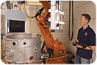
DDA radiography provides image acquisition far faster than traditional film radiography. Source: X-R-I Testing
The digital revolution that occurred in both amateur and professional photography was the direct result of increased recognition that-for most applications-digital works better. Digital radiography (DR) experienced similar rapid growth in clinical use and has spilled over into the nondestructive testing (NDT) arena. While DR technology has been in use for some time, recognition of its merits is somewhat lacking among the NDT film radiography community. There are several types of DR, but the two most commonly used in NDT are computed radiography (CR) and digital detector array radiography (DDA).
Computed Radiography
Computed radiography can be used with X-ray systems that formerly used film, but computed radiography is much faster than film imaging. Computed radiography uses a special phosphor plate or imaging plate (IP) to store the radiation signal not fully attenuated by the test object. The amount of radiation reaching the phosphor plate during exposure translates to more or less signal being stored in the phosphor. After exposure, the IP is scanned with special laser optics to release the hidden or latent image in the phosphor. From there, photo-multiplication, signal amplification and digitization bring the image into a pixellized format. As with any digital image, it can be enhanced with further processing.The IP is erased at the end of the scanning process and is ready for a new exposure. When used properly imaging plates can acquire thousands of exposures that, of course, lead to substantial savings in film and processing costs.
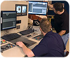
Reusable CR imaging plates eliminate the burden of darkroom, film, chemistry and discharge. Source: X-R-I Testing
Digital Detector Arrays
DDA images are captured with a solid state detector-or panel-that in as little as a few seconds converts and relays the information to the image processor and workstation for display.Portions of the applied X-ray signal completely penetrate the part and interact with a phosphor or scintillator just inside the DDA input window. The phosphor/scintillator layer converts the X-ray signal to visible light. The efficiency of this first conversion directly affects image quality, and different types of phosphors or scintillators are used in the variety of DDAs currently available. For example, a thicker, high-quality cesium iodide scintillator would absorb more of the X-ray signal and provide an improved signal-to-noise ratio.
The phosphor/scintillator layer is in contact with an amorphous silicon thin-film transistor array containing individual detector locations called pixels. High resolution detectors may have millions of pixels, depending on pixel dimension and array (active area) size. Each pixel translates the amount of light received from the phosphor/scintillator into an amount of electronic charge in the amorphous silicon. That charge is then rapidly removed from the transistor array in channels, synchronized, amplified and digitized within the DDA electronics, and finally routed to the system image processor for eventual display at the workstation.
Quite often, multiple images or “frames” are captured during the DDA imaging process. These frames are combined to average out noise and clean up an image. The final raw digital image can be digitally enhanced to improve feature or indication detection, recognition and evaluation.
One area of concern with DDAs is “bad pixels.” These are pixels in the DDA that do not respond properly to the input signal. All DDAs have bad pixels, the extent of which will establish the grade, and eventual cost, of the DDA.
When inspecting high performance hardware-with tight material acceptance standards-pixel size and the frequency and location of bad pixels within the DDA is critical. Several specific procedures and performance evaluations are used to quantify and qualify various DDA metrics, including spatial resolution, contrast sensitivity and retention of radiation signal. Any performance degradation or variation calls for an investigation and determination of any inspection impact.
Dynamic Range
The dynamic range of an imaging system is its ability to detect an extensive thickness or density change in the test specimen, within a single view or exposure. Film radiographs are 8 bit images (8 bit = 28 = 256) that contain about 250 different shades of usable radiographic density (1.50 to 4.00 density). This is a very limited dynamic range compared to most DR systems that, even on the low end, can produce 12-bit (4,096 shades of gray) images, and on the high end up to 16-bit (65,000+) images. The high dynamic range of DR imaging systems, however, means greater sensitivity to scattered radiation, too much of which results in “noise” in the image. There is noise in any imaging system, which must be limited or controlled to maintain contrast sensitivity.Spatial Resolution
In radiographic inspection, contrast sensitivity is important, but spatial resolution (definition) is equally significant. Spatial resolution is the ability to see fine detail. This detail in a radiographic image is closely related to geometry of the technique, which includes distances and X-ray tube focus size. It is also highly dependant on the detector itself.Radiographic film has photosensitive silver crystals or grains about two to five microns in size. Commonly used DR system pixels are usually around 50 to 200 microns, or about 25 to 40 times more than film crystal size range. Therefore, film has inherently higher definition capability than any DR system.
There are certain specialized types of DR detectors with limited active area size that feature pixel sizes down to 10 microns, but those often are limited to specific applications or radiation energies. DR image definition is often enhanced with image processing (zoom) and geometric enlargement (image magnification) techniques. Geometric enlargement in a DR technique always requires an X-ray tube with a reduced focal spot.
Replacing Film with Digital
The incentives to switch from film to digital are to stop buying -commodity-based film, to eliminate the film processor and chemistry headaches, to speed up the radiographic inspection process and to gain more convenient image archives.Of course, the common concern of any radiography professional is, or should be: “Will we find the same size or type of defect with DR that we would with film?” There is no fixed answer to this question, as DR systems relate to film based imaging in only one manner-they both convert the primary signal, ionizing radiation, into readable information. That is where all similarity ends. So the question that must be asked is: “Will this particular DR system meet this inspection requirement?”
There are DR systems that easily surpass the image quality of film. These systems are quite often custom built, using automation, geometric enlargement and high resolution DDAs within the system. Other systems are in use that do not have near film resolution, but fit the application handily.
Any DR imaging system must be evaluated prior to implementation, with system resolution, material form, throughput, ease of operator interface and budget all being considered in the final choice-the benchmark being the detection and accurate portrayal of any substandard discontinuities for a given application.
The Future
In the near future, ASTM will be publishing three long-awaited specifications that will be the final documents needed to cover all the DR imaging modes. There also is an intense effort underway by the Department of Defense to bring DR into widespread use for aerospace component radiographic imaging processes with the intent being lower cost, less environmental impact, image archival and sharing efficiency, and higher throughput.A consortium of prime and key suppliers has been formed to propel and mature DR technology into the current needs of aerospace NDT. This group, known as the Metals Affordability Initiative Consortium, or MAIC, also is running R&D on other Department of Defense related aerospace metal processes for strategic enrichment.
Tech Tips
Digital Radiography in Aerospace
Digital radiography (DR) is being widely adopted in many NDT applications. It provides results that are equal to-and in some cases better than-film radiography while offering significant savings in time, material, processing and archiving costs.The major stumbling blocks to widespread acceptance of digital radiography in the aerospace industry seem to be the historic comfort level with current film imaging processes, a general lack of understanding of the capabilities of digital radiography and, perhaps most important, the uncertainty of customer approval.
To overcome these barriers, the major DR equipment vendors are willing to provide validation studies. They will work with interested parties to demonstrate the efficacy of DR for specific applications.
Customer approval is usually predicated on conformance to specific standards such as Nadcap or ASTM. The Federal Working Group on Industrial Radiography is working with the Metals Affordability Initiative Consortium to develop application guidelines and standards to support the transition to filmless imaging.
Looking for a reprint of this article?
From high-res PDFs to custom plaques, order your copy today!


