NDT | Radiography
Why Additional Training Is Needed When Transitioning From Film Radiography To Digital Radiography
It is essential to have additional formal training to understand key image quality requirements.
Image source: James F. Molinaro Jr./Getty images
Recently, the nondestructive testing industry has made great strides to change their radiography process from film to digital radiography. These changes and advancements have allowed many companies to reduce the overall cost of their RT process and increase production. These are great for any NDT process and company, however, a radiographer needs to recognize and understand the key differences between film and digital radiography.
Many of the industrial standards that govern the qualification and certification of NDT personnel require additional formal training and experience hours (OJT) to transition from film (RT) to non-film or digital radiography. This requirement applies to current or previously certified film Level I, II, or III radiographers.
The purpose of this article is to ask: Is it really essential for well experienced certified film radiographers to receive additional formal training and experience? After all, radiography is radiography. In my opinion, the answer is yes! It is absolutely essential to have additional formal training to understand key image quality requirements of both the computed radiography (CR) and digital radiography (DR) systems used in digital radiography! I’m not saying that because I am an NDT instructor, nor am I writing this article to discourage film radiographers from converting their film process to digital. My goal is to educate you on key items to consider prior to making a purchase. In my experience, I have seen a few occasions where companies spent hundreds of thousands of dollars on CR systems to find the system doesn’t meet the requirements set forth by their customers.
I always tell my experienced film certified students that they already possess the knowledge and fundamentals of film radiography. Most of these are still relevant, but now they have to learn new image quality calculations, terms, and acronyms used in digital radiography. I often say it is comparable to learning a new language and my job is to make you bilingual in both film and digital radiography.
Today’s qualification and certification standards used within the NDT industry require current and previously certified film radiographers to receive additional formal training and experience hours to transition their certification to include digital radiography. For example, SNT-TC-1A recommends that current level 2 radiographers need 24 hours of additional training (16 hours equipment familiarization training and then eight hours of formal training). NAS410 requires current film level 2 radiographer to receive 40 hours of formal training in non-film, and 200 hours of experience. Personally, I agree with the requirements of additional formal training and experience because of new technical items and subject matter involved with digital radiography that was not considered or applicable for film radiography.
Although X or Gamma Ray fundamentals still work within digital technology similarly as with film, a radiographer must be aware of the limitations of digital radiography (DR/DDA) and computed radiography (CR) systems.
Basic Spatial Resolution
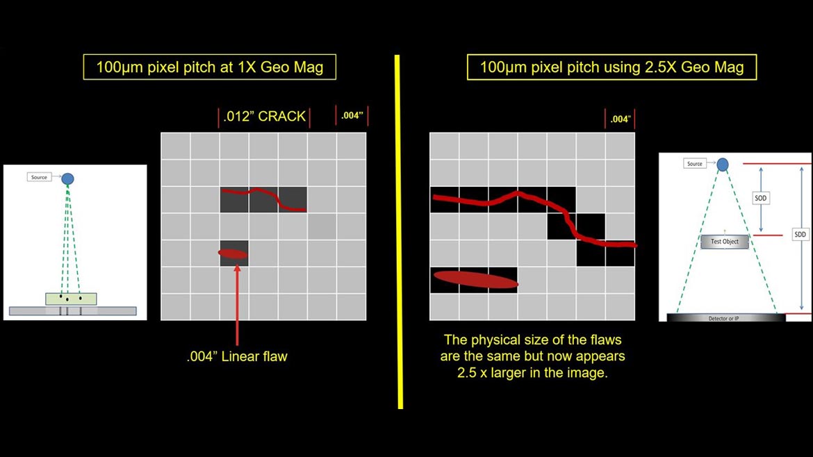
One of the most important characteristics when selecting a CR or DR system is the basic spatial resolution. Basic spatial resolution is defined as the smallest degree of visible detail within a digital image that is considered the effective pixel size. This measurement aids in determining if a digital system is capable detecting the smallest size flaw required to be viewed in the radiograph. Film has always been the gold standard for resolution within the NDT industry. Film is still considered to have better inherent spatial resolution than CR and DR when placing a test object directly on film, CR imaging plate or DR flat panel detector. Many automated DR systems use geometric magnification to replicate resolution achieved with film, however this is only possible with a mini-focus (< 1mm focal spot) or micro-focus (< .1mm focal spot) X-Ray tube. This may not be an option for companies that use conventional X-Ray tubes (~1 to 7 mm focal spot) with larger focal spots for their film process. Using geometric magnification with conventional X-Ray Tubes would result in the radiographic image to be very blurry or unsharp. Detecting flaws are almost impossible with this situation.
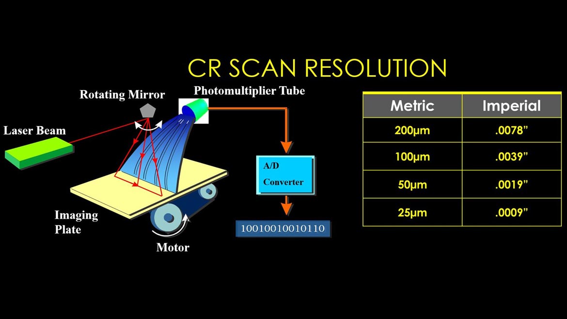
While using a CR system, the operator can choose to scan the imaging plate at a specific pixel pitch (i.e.,100, 50, or 25-microns). Will this result in the image having a basic spatial resolution of 100, 50, or 25-microns? No, depending on the CR scanner performance and imaging plate characteristics there can be approximately a 15 to 55 micron larger measurement in SRbdetector.
All images courtesy of James F. Molinaro Jr.
Even with indirect DDA flat panel detectors of a specific pixel pitch (i.e., 75, 100, or 200 micron) the actual SRbdetector can be approximately 5-50 microns larger than the listed pixel pitch. Indirect DDA flat panel detectors typically use either a Cesium Iodide or Gadolinium Oxide scintillator to convert the X or Gamma Ray photons into a visible light that is measured by the photodiode array of the Amorphous Silicon TFT substrate. The thickness of this scintillator does influence the SRbdetector and basically, the thicker the scintillator is, the larger your SRbdetector measurement will be, while a thinner scintillator will have a slightly larger SRbdetector than the listed pixel pitch. The thickness of the scintillator is typically dependent on the intended application (i.e., material type and thickness). There are advantages and disadvantages when choosing a thinner or thicker scintillator. Most manufacturers will help you decide which scintillator best suits your application.
Image Unsharpness
One of the most critical calculations used in the film radiography process is known as Geometric Unsharpness (Ug). Ug is the measurement of the blur (aka penumbra) in a film radiograph. If this measurement is above the value stated in the standards, the radiograph will lack the definition or sharpness required to find flaws. This measurement is calculated by knowing the source to object distance (SOD), object to film distance (OFD), and focal spot size of the X or Gamma Ray source.
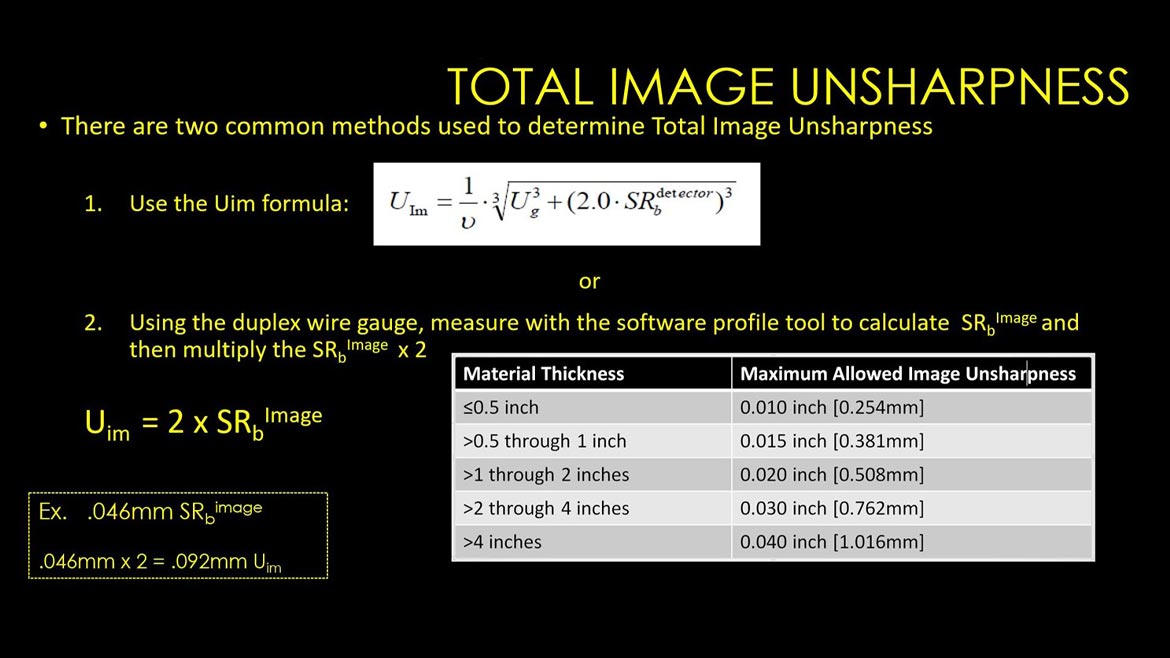
Ug is still a factor with digital radiography, however there are more image attributes that also need to be considered. We must consider (Ug) Geometric Unsharpness, but now we need to know the (SRbdetector) basic spatial resolution of the detector, and what the geometric magnification (Distance from the top of the part to the detector) is. We refer to the combination of these attributes as Image Unsharpness (Uim). This calculation/formula is new to an experienced film radiographer.
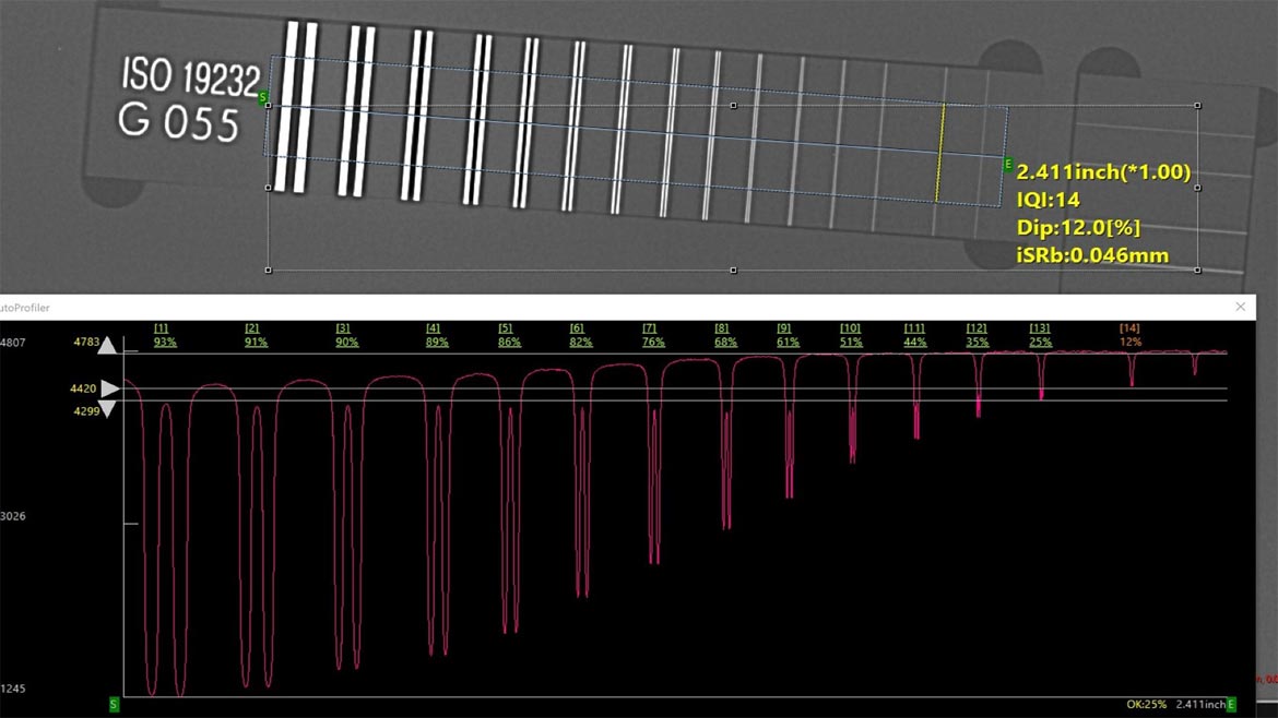
There are two common methods used to calculate this measurement. Method One is to use the Duplex Wire Gauge per ASTM E2002 or Method Two is to calculate with the Uim formula listed in ASTM E2033 & E2698. If radiographers are not aware of this requirement and use only the (film) Ug formula, they could produce a digital radiograph that is missing the definition or sharpness required to locate flaws.
Pixel Coverage
When using CR or DDA it is important to know if you have enough pixel coverage for the flaw size needed to discern. When purchasing a DDA System pixel pitch is extremely important value to consider.
If pixel coverage is not sufficient, you may be able to use geometric magnification to achieve pixel coverage and Uim that’s required. Again, to use geometric magnification a mini or micro focus X-Ray tube will be needed.
ASTM E2736 has a recommendation regarding the minimum number of effective pixels to cover the longest dimension of a defect. The recommendation states that >6 pixels covering the longest defect is the best practice if available. Keep in mind that the SRbdetector is the measurement used for this recommendation and not the pixel pitch or CR scan resolution.
Text from ASTM E2736. Source: ASTM
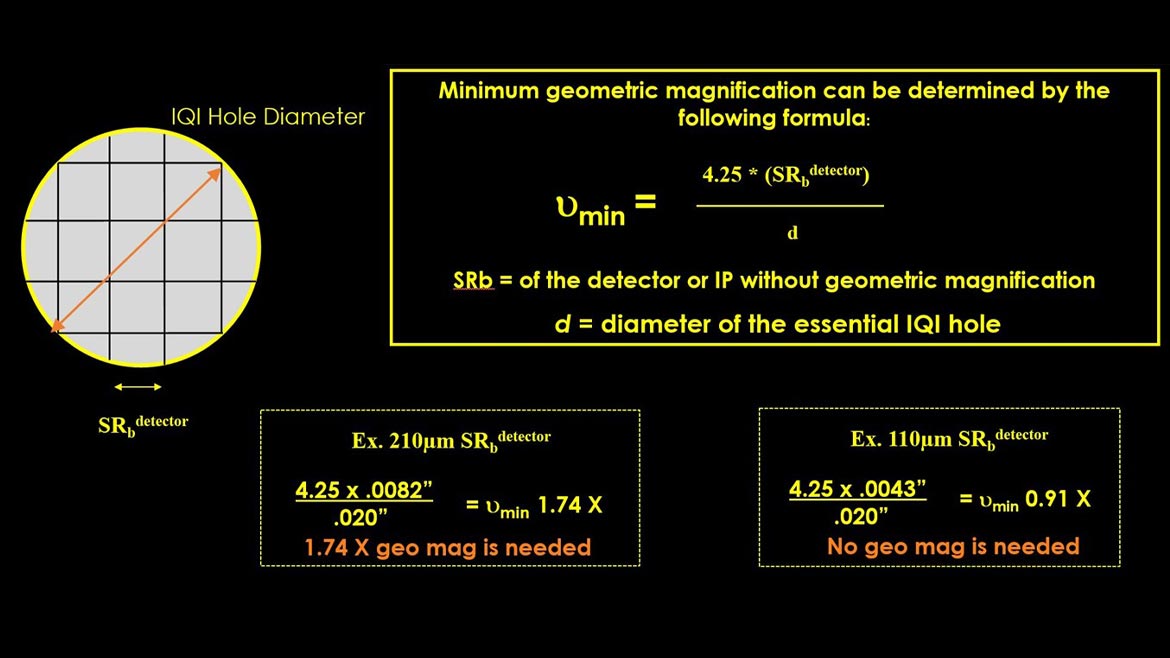
Many aerospace manufacturers use the 3x3 pixel matrix rule to determine if it needs any geometric magnification to compensate for the lack of pixel coverage. Basically, a 3x3 pixel matrix needs to fit inside the smallest penetrameter essential T-hole size. If this is not achievable, geometric magnification will be required or you will have to select a CR or DR system that has a smaller SRbdetector measurement.
Previously, I’ve witnessed companies purchase digital systems based upon price tag instead of system capabilities. They meant well, attempting to save the company money, but later found their customers wouldn’t approve the new system due to not having enough pixel coverage and/or meeting qualifying requirements.
Summary
These items are just a few examples of why additional formal training and experience in digital radiography is beneficial. I highly recommend having manufacturers demo their digital systems at your facility using your existing X-Ray tube and an actual part with the smallest defect that is to be detected. If you are only familiar with film radiography, I highly recommend having a consultant educated in digital radiography prior to making any system purchases. As part of the purchasing decision, the manufacturer should provide Spider Charts for their systems as listed in ASTM E2446 & E2597. Spider Charts show the performance characteristics of their digital system (ex. SRbdetector , Contrast Sensitivity, Signal to Noise Ratio, MTR, EPS,etc.).
Looking for a reprint of this article?
From high-res PDFs to custom plaques, order your copy today!


