Blue Light Optical Scanning for High Resolution 3D Measurement
When an entire shape needs to be scanned, optical measurement is more effective.
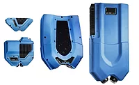
ZEISS COMET L3D 2 measures contour by triangulation between the single camera and the projector. Source: ZEISS
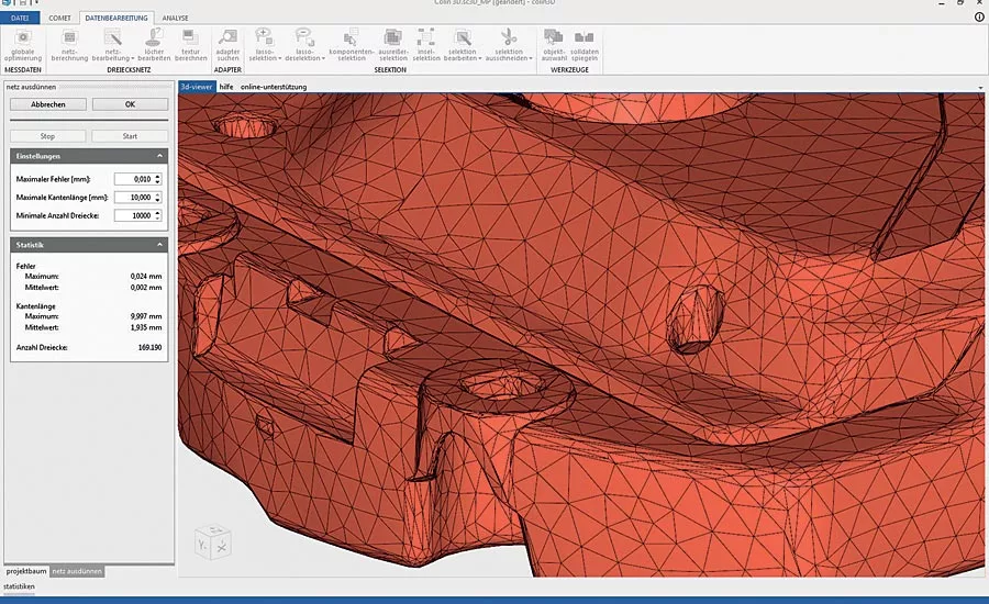
Quick triangle mesh generation using high-quality data reduction. Source: ZEISS
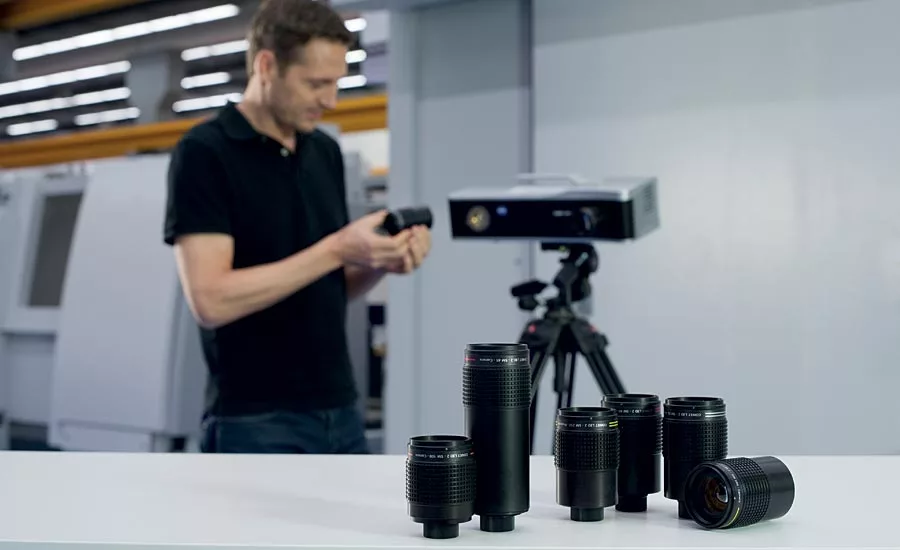
Cameras and projectors use interchangeable lenses to cover a range of different-size fields of view. Source: ZEISS
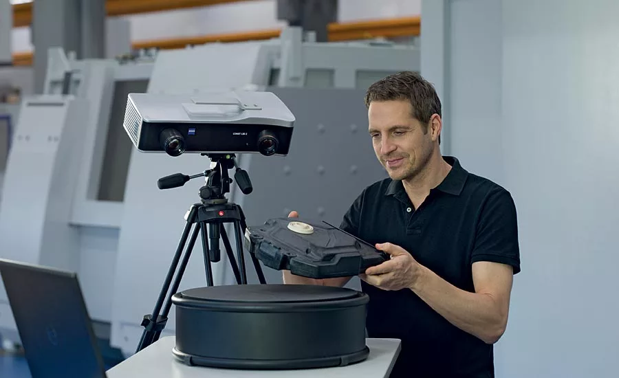
There are a variety of ways to perform automated, high precision measurement, each with its own strengths. Contact measurement is more effective for measuring specific features—holes for example—to ensure that they are where they belong and of the correct shape and size. When an entire shape needs to be scanned, for example to reverse engineer a part, optical measurement is more effective. Optical technology delivers a complete, detailed picture of a surface. And because optical scanning images cover an entire field of view rather than one point at a time, they can be made very quickly.
Seeing Depth and Contour by Triangulation
Recognizing contour is a matter of judging relative distance from a fixed point, but this cannot be done based solely on a single point of view. As a human, if you close one eye you lose depth perception and cannot effectively judge distance or contour. Our human ability to judge depth is based on seeing the same object through two eyes, each from a different angle. We then mentally “triangulate” to determine relative distance to each point on an object’s surface and, by extension, its contour.
The same effect can be seen in a “wire frame” image created, for example, in a CAD model. The lines projected on the contoured surface of a curved model may appear straight if the object is viewed perpendicular to the surface. But as the object is rotated away from that straight-on view, those lines begin to curve, showing the contour of the surface. That is what is done in optical scanning.
Red Laser vs. Blue Light Scanning
There are several technologies in use today for optical scanning. The two major options are red laser scanning and blue light scanning. Red laser scanning is simpler and typically requires less training. It can even be done using a handheld device. It is, however less precise, particularly for use on reflective surfaces. Blue light’s shorter wavelength makes it suitable for many reflective surfaces, and its homogenous frequency range makes it more precise than white light.
Blue light technology recognizes contour by triangulating the line of sight of a photographic lens and the line of sight of a light source that projects a “fringe” pattern onto the surface being measured and then uses software to convert multiple images into a three dimensional representation. This is essentially a photographic process that, depending on the vendor, involves a fringe pattern projector and either one or two cameras. In either case, the object being scanned is turned using a high-precision rotary table to allow a full 360° representation. In some cases, after being scanned through a full 360°, the object is turned and then scanned through the full rotation again to achieve a spherical, rather than just cylindrical, view.
Single vs. Multiple Cameras
The problem with multiple cameras is that their view is only effective where their respective fields of view overlap. For this reason two cameras can actually provide a narrower field of view than a single camera does. If the purpose of two cameras is to provide triangulation to measure contour, that function is served in a single-camera design by triangulation between the single camera and the projector. And because two cameras have slightly different views of the subject, the resulting measurement can potentially be less sharp than the single WYSIWYG image produced by a single camera.
Cameras and projectors use interchangeable lenses to cover a range of different-size fields of view. This allows inspection of anything from a very small part to an entire vehicle. When lenses are changed, and in other cases as well, the camera must be recalibrated to ensure maximum precision. For obvious reasons, lens change and recalibration are simpler processes in a single camera setup than when dual cameras are used.
Image Resolution
Resolution of the scanned image is determined by a combination of selected field of view and the resolution of the camera itself. A 16 megapixel camera, for example, would have higher resolution than a five megapixel camera if both were using lenses providing the same field of views. The lower resolution camera, however, could match the image resolution of the higher resolution camera by reducing its field of view for each individual image. That would require a larger number of images to create the final 3D image and significantly slow the process.
A lower resolution camera costs less and would be perfectly adequate if only a relatively small object were to be scanned. It would also work for scanning larger objects at high resolution if time were not an issue.
Creating the 3D Image
The blue light scanner’s software combines multiple scanned images into a 3D surface image that can be stored, rotated, expanded, and otherwise examined to evaluate a part or assembly. The software creates a “point cloud,” a cluster of points representing the scanned object. The camera and field of view determine the density of points, essentially pixels representing the virtual object. The software algorithm eliminates overlaps among the individual images to create one seamless data set in the STL (stereo lithography) format. STL files can be used for inspection and quality control, tool and model making, reverse engineering, rapid manufacturing and more.
The challenge for the software is recognizing the points of overlap among the multiple images. In some systems this is achieved by attaching visible “targets” to the item being scanned in much the same way that a cinematic “motion capture” system places visible targets on an actor in front of a green screen and then process the video image to create a character in a setting following the actor’s movements.
In the same way, the optical scanner’s software matches the targets in adjoining images to position the component images into the complete final image. Attaching and removing targets takes time, and they must be properly positioned to ensure that all of the images can be integrated into the final image. The alternative approach is to use software that can recognize features of the scanned object itself, defining those as its targets, and using them to align the individual images. This method requires somewhat more sophisticated software, but it simplifies the scanning process and ensures maximum accuracy.
Conclusion
Optical scanning is the technology of choice for capturing surface contours of an object. Decisions in choosing a system include:
- Red laser vs. blue light, blue light being the more precise of the two
- Single or dual cameras
- Camera resolution
- Attached targets vs. feature recognition for image matching
- General software capabilities
Looking for a reprint of this article?
From high-res PDFs to custom plaques, order your copy today!