Design Considerations for New High Resolution and Frame Rate CMOS Sensors
Sensors will continue to evolve, and camera lenses will continue evolving right along with them.

Figure 1: The cross-section of the back of a C-mount 1.1” high resolution 12 mm focal length lens. Note that due to the supporting mechanics, including the camera mount, inner barrel, and retaining mechanics, the maximum lens diameter of the last lens is much smaller than the 25.4 mm C-mount opening. This results in a steeper ray angle.
Lens and camera sensor technology tends to co-evolve. As cameras drive to smaller and smaller pixel sizes with growing formats, lenses need to be designed to match those higher capabilities. However, they evolve at vastly different rates from one another, with the advancement of sensor technology vastly outpacing that of optics. Commercially available cameras using CCD imaging sensors were only developed in the 1970s (by Kodak-Eastman1), and at the time optics technology had been around for hundreds of years. As a point of reference, Galileo designed his eponymous telescope in 16102, and photography started in the late 1700s3. While optics had a pretty large head start, sensor technology would only take about 30 years to match, and then surpass, what optics were capable of in terms of their ability to resolve small pixels.
From a fundamental perspective (ignoring new advancements such as optical metameterials and their negative refractive indices), optics technology has not changed since lenses first started being used. Essentially, the ability to design and manufacture more precise optical components and systems have improved greatly, but a lens is still a lens. It is now commonplace to see sensors in the industrial marketplace with over 20 megapixel (MP) resolution at a reasonable price and with good performance, all packed into a C-mount housing, representing a 2000X increase from the first CCD sensor invented1. Optics have not advanced this far in the same time period.
There are two ways that sensors can increase their resolution: pixel size can get smaller, or the sensor can grow in size while keeping the pixel size the same. There are tradeoffs with each of these methods; typically, smaller pixels tends to mean a lower signal to noise ratio (SNR) when compared to larger pixels, but larger sensors tend to be more expensive. The general trend, however, tends to show sensor sizes increasing, even as pixels continue to decrease in size. The machine vision industry is at an interesting time currently, with sensor sizes maximizing what a C-mount is physically capable of. C-mount is a camera standard that defines a 25.4 mm threaded mount with a back flange distance (often referred to as a flange focal distance or simply flange distance) of 17.526 mm.
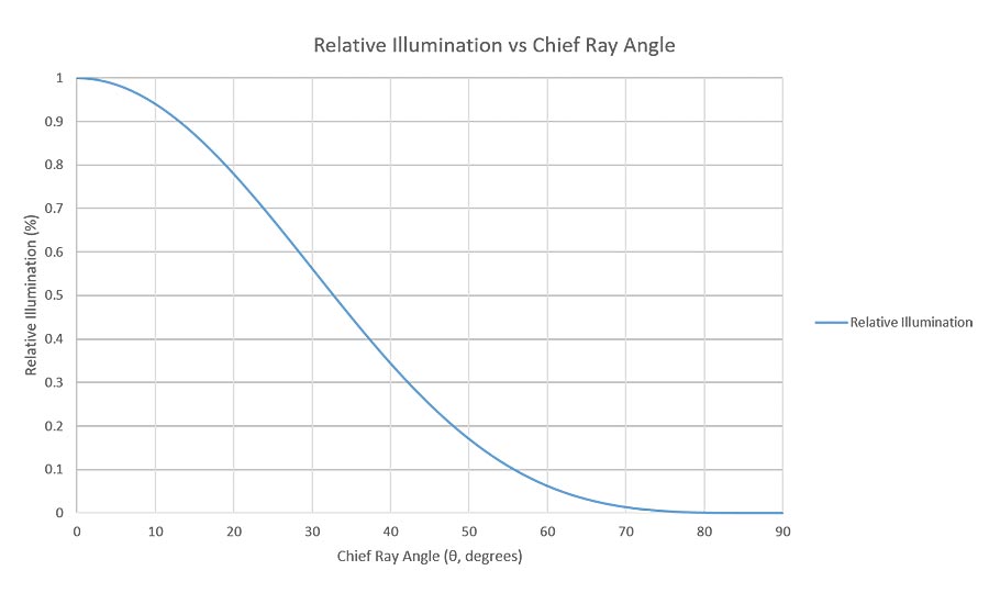
Figure 2: The impact of chief ray angle on relative brightness on an image sensor. Large sensors in C-mount cameras exacerbate this problem.
As shown in Figure 1, the maximum diameter that an optic can achieve in a C-mount housing is around 17 mm, despite the opening being 25.4 mm. This is due to the fact that the lens has mechanics of its own that need to accommodate the main lens barrel, the focusing inner barrel, and a retainer to hold the optics in place. Each of these steps reduce the size of the available clear aperture of the optical elements in the lens assembly. As the size of the optics decreases, the angle at which the light must come out of the lens grows. This is not a problem when sensors are smaller than the size of the optics, but as sensors increase in size, it becomes more difficult for the optics to pair up well with the sensor inside of a C-mount. As this angle (θ in Figure 1) increases, the corners of the image become much darker due to cos4(θ) roll-off4. Figure 2 shows this fall-off relationship with respect to angle. In an optical design, minimizing this angle is of high priority. All of this together essentially limits the size of a sensor in a C-mount camera to a 1.1” format (17.6 mm diagonal).
The third generation release of Sony’s Pregius came with the IMX342, which is a 32 MP sensor in an APS-C format (28 mm diagonal). This sensor is far too large for a C-mount. However, it is in an interesting space for the industrial marketplace, as this sensor is too small for an F-mount, which is the next size up and has several optical problems associated with it. M42 is a potentially logical option, and cameras already exist with M42 as a lens mount, though there exists no commonly accepted standard that the camera industry adheres to that makes this option viable (with varying flanges and thread pitches). TFL, however, is the perfect mount for a sensor of the APS-C size. A TFL mount is M35x0.75 mm, with a 17.526 mm flange distance5; this is the same flange distance as the C-mount. Because of this, it can be thought of as a larger diameter C-mount.
The TFL mount has several advantages over F-mount for an APS-C sensor size. These advantages are in overall size, flange distance, and the way that the lens is secured into the lens mount on the camera. F-mount lenses tend to be large when compared to C-mount lenses. This is mostly due to the fact that they cover larger sensors. Figure 3 shows a comparison in size between a 29 MP F-mount system and a 32 MP TFL-mount system. Note the differences in size between the two systems for a comparative resolution. While this article will not detail the differences between the two systems, it is sufficient here to note the size difference, which also equates to a cost difference in the lens. As lenses grow in size, they grow more expensive as well; a rough rule of thumb would indicate that the cost for a single lens element grows with the radius squared. Extrapolated over several elements, it is easy to see how larger lenses are more expensive.
Another major advantage of the TFL-mount solution over an F-mount solution is the flange distance. As mentioned above, the TFL-mount can be thought of as a larger diameter C-mount because they share the same flange distance of 17.526 mm. F-mount has a flange distance of 46.5 mm. The long flange distance of the F-mount limits the type of optical design form that can be used. This is especially true for shorter focal length lenses, which tend to have shorter back focal lengths (Back focal length, or BFL, not to be confused with a flange distance, is the distance from the last optical element to the image plane) as well.
Making a short lens with a long BFL forces the lens to be designed as a reverse telephoto, which is to say a lens with a focal length that is shorter than the overall length of the lens. Forcing a lens into this design paradigm inherently causes tradeoffs to be made with the design in terms of resolution. This can, in certain circumstances, be overcome with lenses that have a larger rear protrusion, meaning that the lens protrudes into the camera housing. However, lenses with large amounts of rear protrusion tend to need to reduce their diameters substantially in order to properly fit inside the camera body, leading to the same cos4(θ) issues listed above. The shorter flange distance of the TFL not only contributes to an overall shorter system, but allows the optical designer a lot more freedom when designing to maximize the resolution of the lens.
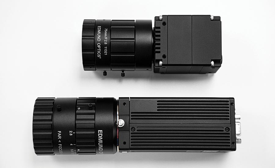
Figure 3: The difference in size between an imaging system with 32 MP resolution with a TFL-mount camera/lens (top) and an imaging system with 29 MP resolution with an F-mount camera/lens. Note the size difference between the two systems for comparable resolution.
This smaller flange distance, coupled with the fact that TFL lenses will be designed for smaller sensors and hence be less impacted by field-dependent aberrations, means that lenses designed for TFL mount cameras will be higher performing in a smaller package size, and will be more cost-effective.
Lastly, an F-mount is not a threaded mount; rather, it is a bayonet mount. Bayonet mounts are great for photography, as they allow the user of the camera to swap lenses out quickly and efficiently for different scenarios, and allows for the easy integration of electronic features (iris/focus control) since they are a clocked mechanism. However, for the majority of applications in machine vision, these advantages are not really advantages. Lenses are rarely (if ever) replaced, and if they are it is not in a time sensitive manner. Iris control is useful in corner case applications, but it is usually fixed, and relying on servomotors/micro motors with moving parts to focus a lens in a factory environment millions of times is likely going to lead to parts wearing out. The major disadvantage of the bayonet mount, however, is simply the nature of the bayonet mount itself. As sensors grow in size, the amount of allowable tilt of the sensor with respect to the optical axis becomes smaller.
Figure 4 shows how tilt in the image plane with respect to the optical axis impacts larger sensors more. Keeping the tilt numbers small is imperative to ensuring high optical performance, especially given low f/#s, which are required for high resolution applications. The bayonet mount allows for more tilt in the imaging system, and doesn’t pair the lens and camera together in an optimal way.
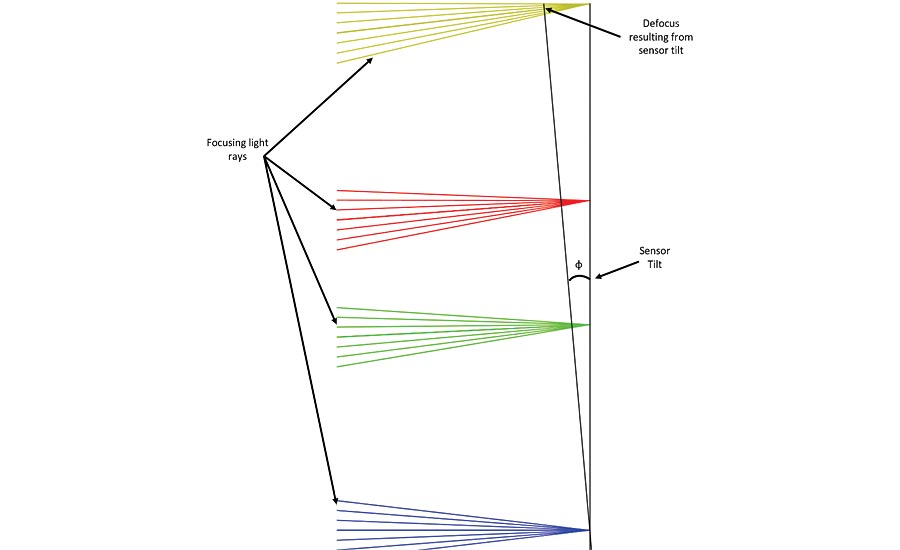
Figure 4: Light rays focusing on an imaging sensor. The blue rays represent light at the center of an imaging sensor, green represents the corner of a 1/2” sensor, red represents the corner of a 2/3” sensor, and yellow represents the corner of a 1.1” sensor. Note that the same amount of tilt is more impactful on a larger sensor
With TFL mount lenses being smaller, lighter, less expensive, and higher resolution than F-mount lenses, they are certainly the better choice for APS-C sensors. While the standard is still gaining in popularity in the machine vision marketplace, and it will be some time until they are as ubiquitous as the F-mount, they are a promising new take on the optics and cameras that are used every day. Sensors will, of course, continue to evolve, and camera lenses will continue evolving right along with them. Sensors are already on the market such as the Canon 120 MP sensor that are too large even for a TFL-mount (and more suitable to a TFL-II5), and lenses will need to be designed that can handle these ever-increasing resolution requirements. V&S
Sources:
- van Hall, Dennis, “History of The Digital Camera and Digital Imaging,” www.digitalkameramuseum.de/en/history (2015)
- Plotner, Tammy, “What is Galileo’s Telescope?,” https://www.universetoday.com/15763/galileos-telescope/ (2016)
- “Thomas Wedgwood Biography - A Pioneer of Photography,” http://www.photographyhistoryfacts.com/photography-inventors/thomas-wedgwood/ (2019)
- Max Reiss, “Notes on the Cos4 Law of Illumination,” J. Opt. Soc. Am. 38, 980-986 (1948)
- The Standardization Committee—Lens Working Group, “TFL Mount and TFL-II Mount Standards and Operational Regulations,” Japan Industrial Imaging Association, 3 (2017)
Looking for a reprint of this article?
From high-res PDFs to custom plaques, order your copy today!


