Why the CLHS Interface is a Boon to Manufacturing
Of all the machine vision standards available on the market, the Camera Link HS (CLHS) protocol leads in reliability, cost, and throughput.
The manufacturing industry is a very competitive environment. Customers demand the highest quality at the lowest cost and are able to easily search a global economy for that perfect component. For leading manufacturers to remain competitive, they must continually adopt the latest technology, as this will enable them to deliver higher quality products at lower costs. Machine vision is an integral part of a high-quality production process. Of all the machine vision standards available on the market, the Camera Link HS (CLHS) protocol leads in reliability, cost, and throughput—and most importantly supports fiber optic cabling. This latter feature sets CLHS apart because of the immense benefits fiber optic cabling brings to the manufacturing industry.
Smart Cameras vs. Traditional Vision System
“Smart” cameras are usually the go-to solution for industrial engineers because of their small size and ease of use. These cameras include an image sensor, an internal processing unit, and often feature built-in algorithms, and are designed for specific tasks like bar code reading, or pattern-matching. Often, these cameras include a lens and lighting which further simplifies the system design. Unfortunately, typical “smart” cameras can only handle simple tasks at relatively low throughput.
For more complex applications or high-volume manufacturing, a more traditional vision system may be required for its increased processing power and a higher throughput rate. These conventional systems include a camera, with associated lens and lighting, image transmission technology, and a PC for image processing. The image transmission technology is particularly important because it can ultimately limit the capabilities of the vision system.
Cost/Performance Trade-offs in Vision Standards
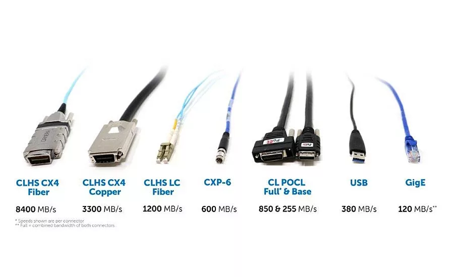
Each of the vision standards has unique capabilities or cost/performance trade-offs. The reason there are so many image transmission technologies available is a result of advancements in telecommunications and PC communication technologies, the wide range of applications and needs in manufacturing, continued use of established, older technologies due to familiarity, and the large number of available products that use the legacy standards. Some of the most popular image transmission technologies are: GigE Vision, Camera Link, Camera Link HS (CLHS), CoaXpress, and USB Vision. These standards are differentiated by:
- Their use of a PC or telecommunications plug-in cards (GigE and USB) vs. protocol-specific cards
- The connector and cables used to transfer image data from camera to PC
- The distances supported by those cables
- Camera-triggering capabilities
- Protocol features, such as transmission error correction, support for GPIO, and other real time features
More detailed information about each standard can be found in the Global Vision brochure available from https://www.visiononline.org/vision-standards.cfm.
The Advantages of CHLS to Manufacturers
Of all these standards, CLHS offers the best set of advantages to manufacturers. As compared to other protocols that don’t offer error correction/detection capability, the CLHS protocol corrects errors immediately, ensuring that products are inspected accurately. This assures manufacturers and end-user customers that their products are free from undetected defects.
CLHS cables have the highest bandwidth. CLHS uses both copper cabling for short distances (to 15 meter, 3.125 Gbps/lane for cable bandwidth of 2.1 GByte/sec), plug-in fiber optic cabling for longer distances, and higher bit rates (10.3125 Gbps/lane for cable bandwidth of 8.4 GByte/s). CLHS is the only standard that explicitly supports fiber cabling. This is an ideal choice for industrial engineers designing moving platform systems, such as robotic arms, because the fiber optic cable is much lighter than copper and easier to move. Also, in comparison to copper cables that suffer from induced noise by the flexing/deformation of the cable, fiber has a much higher flex life (over 50 million flex life has been achieved), and this helps ensure reliable image transmission and inspection results. Additionally, fiber optic cabling is immune to “ground bounce” and so should be chosen for long distances. Ground bounce affects long cable runs and can result in transmission errors.
Running copper data or control cables near motors may result in induced bit errors due to electromagnetic radiation. Optical fiber’s inherent immunity to electromagnetic radiation means that it is the preferred transmission medium when running cables near motors.
Cost Benefits of Fiber Optic Cabling
Fiber optic cabling is now lower in cost than coax cabling and is comparable in price to a Cat5E cable. Searching the internet, a reputable seller offers 2 SFP+ modules + 30 meter of LC cabling for $52. Referred to as the F2 connection in CLHS, it supports up to 1200 Mbyte/s of effective data throughput and is much cheaper than Camera Link and CoaXpress solutions. The cable can reach 300 meters, a distance that puts it ahead of other standards in the market. A side benefit of fiber cabling systems is the upgradability of the installed fiber. Today, 10.3125 Gbps is very cost effective but modules and FPGAs are available that support 28 Gbps, achieving 3000 Mbyte/sec over the same fiber cable. Copper cabling reaches its limits at these bandwidths due to the skin effect and signal loss, making it very difficult to increase the bandwidth/system performance on existing cables. New systems should therefore specify fiber optic cables as the interconnect.
Image Processing
Processing images at high bandwidth requires that the image be split among multiple PCs. CLHS cost-effectively achieves this by defining an asymmetric bandwidth cable having 7 down lanes and 1 up lane. We have shipped product using the C2 connection running at 3 and 5 Gbps, resulting in 2.1 and 3.3 GByte/s of image throughput. Most systems use copper cables because 15 meters is sufficient, but for those systems requiring longer distances of up to 100 meters, plug-on Active Optical Cables (AOC) are available from Alysium and Hewtech. Our latest generation of product run the cable at 10.3125 Gbps and use the CLHS X protocol (64/66 encoding with Forward Error Correction) for an effective image bandwidth of 8.4 GByte/sec in the single cable. To process the image at these rates, the frame grabber enables the unused FPGA transmitters connected to a data forwarding connector. The data is forwarded over low-cost 1-meter copper cables to neighboring PCs. The CLHS protocol has features to synchronize multiple frame grabber cards from the camera, simplifying system setup.
Additional Features of CLHS
Camera triggering is a key requirement for machine vision systems, and CLHS supports a trigger message in the protocol with 6.4 ns of pk to pk jitter, with a latency of under 500 ns. This is the best of any packetized protocol. CLHS is able to control multiple integration times with its trigger message, which is useful in color cameras or wide dynamic range applications. Again, this feature is unique to the CLHS protocol.
CLHS has additional features in its trigger message that command the camera to switch synchronously to new operating conditions with the trigger message. The decision to change operating condition can be based on the results of the previous frame. This feature is not available in other protocols. The camera operating condition is returned in the video message header so that the host can confirm the switch and correctly interpret the data. Alternatively, the operating condition changes can be controlled by GPIO directly connected to camera.
Line scan cameras are fast approaching 300 KHz line rates, having line times of 3.3 us. A 6.4 ns jitter in the line time results in 9-bit performance, as observed by the row-to-row amplitude variation when the exposure time is the full line time. The integration time jitter can be avoided with CLHS protocol by using trigger mode 4,5, (mono) and 6,7 (color) where integration and line times are sent via count values referenced to the image sensor’s clock space. Line scan cameras will get even faster as there are some CMOS sensors with line rates of up to 2 MHz, and this feature will become even more critical in the future.
CLHS includes 16 GPIO signals in each direction with a latency of under 500 ns. This is sufficient response time to enable control of manufacturing peripherals (e.g. reject paddles) and can reduce the cost of system cabling, especially when the distances approach 300 meters. This performance level is not available in other image protocols.
In summary, machine vision is a key technology in the competitive manufacturing environment. New systems will benefit from choosing fiber optic cabling and protocols that meet the system’s requirements today and tomorrow. CLHS has the cost, bandwidth, reliability, and feature set needed for manufacturers to ship top quality product today, with little expense to upgrade for tomorrow. V&S
Looking for a reprint of this article?
From high-res PDFs to custom plaques, order your copy today!


