8 System Performance Tools for Magnetic Particle Inspection
Learn more about magnetic particle inspection tools and requirements.
To demonstrate proper magnetization, first you need to know what’s in the procedure.
This article will list and explain why each magnetic particle inspection accessory is needed to validate the system performance of an inspection.
Magnetic Particle Test Pieces
Whether you are in the automotive or aerospace industry, system performance checks are crucial for an optimal inspection. A system performance check needs to be run daily to validate the capability of the system to magnetize and create indications for examination. A standardized test piece, an example part with known defects, or a part with artificial defects attached to it, all can be used to perform the system performance check. Details of the procedure vary with the type and configuration of equipment being used.
Tool Steel Ring (AS5282)
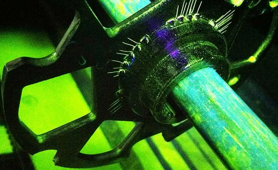
The tool steel ring is a standardized test piece commonly used with wet bench magnetic particle equipment. The ring is machined from AISO O1 tool steel, annealed, tested and certified to meet AS 5282 specifications. Typically used with a ½ inch (1 cm) central conductor, the tool steel ring has 12 machined holes at increasing depths from the edge and is used to verify the performance of HWDC, FWDC, and 3-phase FWDC magnetizing equipment. Suitable for use with wet or dry materials and visible or fluorescent particles. The number of indications required depends on the waveform and magnetizing current amperage (refer to ASTM E1444 or E3024 for more information).
MPI Test Bar
The MPI test bar is a standardized test piece that can be used with wet bench magnetic particle equipment, power pack coil wraps, or magnetic yokes. The test bar has both surface and sub-surface flaws for use with AC, HWDC, FWDC, and 3-phase FWDC magnetizing equipment. Surface EDM notches in two directions allows the test bar to be used to confirm both circular (head-shot) and longitudinal (coil-shot) magnetization.
Quantitative Quality Indicators (QQI)
See quantitative quality indicators (QQI) in action, including basic steps to test for artificial defects and verify field direction and relative strength at www.youtube.com/watch?v=m1MfAd1mIvU.
Field Indicators
For a valid magnetic particle inspection, sufficient magnetic field must be applied to the part to magnetize the area being examined. Although the magnetic field within the part cannot be measured directly, several accessories are available to confirm that sufficient magnetic field is present. Meters and gages may also be used to confirm the level of demagnetization after inspection is completed.
Hall Effect Meter, Gaussmeter, & Flux Meter
The Hall Effect Meter is a calibrated digital meter for measuring the strength of an applied magnetic field. A calibrated sensor probe is placed normal to the surface being examined and responds to the magnetic field tangential to that surface. The meter then provides a reading of the field strength in Gauss, Tesla, or amp/meters, accurate to +/-3%. The Hall Effect Meter has multiple functions, including AC (RMS) and DC (Peak) modes, auto-range and auto-zero, and Min/Max/Peak hold.
Magnetic Field Gages & Magnetometers
Magnetic field gages are portable analog gages commonly used to quickly check for magnetization or demagnetization levels. Available in multiple ranges, a calibrated field gage responds to the inherent or retained magnetic field within a part, accurate to +/-5%. Non-calibrated field gages are also available as a quick go/no-go check for whether a part is magnetized or if it has been demagnetized.
Magnetic Flux Detection
Magnetic fields are directional in nature, and only discontinuities that are orthogonal to the lines of flux will induce leakage fields and form magnetic particle indications. The direction of the magnetic flux is just as important as the strength of the applied magnetic field. Several accessories are available to verify the direction of the magnetic flux within a part under test.
Laminated Flux Strips
Learn about laminated flux strips at https://magnaflux.com/Magnaflux/Resources/Blog/Flux-Indicators-and-QQIs.
For a valid magnetic particle inspection, sufficient magnetic field must be applied to the part to magnetize the area being examined.
Pie Gages
The pie gage is a tool for quickly verifying the direction of magnetic flux on a surface. It is made from eight ferrous segments, braised into a single piece, providing a star pattern of non-ferrous discontinuities. Typically used with dry powders for yoke inspection, the pie gage can be held at any angle and will generate indications perpendicular to the direction of the magnetic flux. A similar test gage, the Berthold Penetrameter, is commonly used in Europe. The Berthold Penetrameter uses four instead of eight ferrous sections, but it is used the same way as the pie gage. While these devices are useful for checking the direction of magnetic flux, they are not considered adequate for demonstrating magnetic field strength.
Concentration Measurement
When using wet materials, the concentration of magnetic particles in the liquid vehicle must be maintained at the right levels to create indications. Different accessories are used to measure the concentration depending on the type of magnetic particles being used.
Centrifuge Tubes
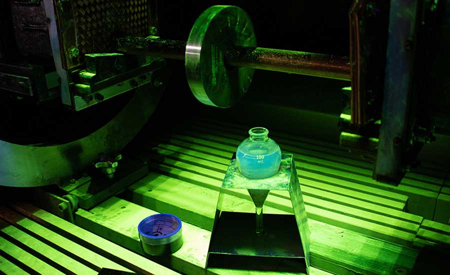
When using wet method materials—either water or oil—the ability to form clear indications is directly related to the concentration of magnetic particles. Different types of particles are effective at different concentration ranges. The magnetic particle centrifuge tube, also known as a Goetz tube, provides a means of verifying the particle concentration as well as evaluating the carrier quality and level of contamination present. The tube is filled with agitated solution and set aside for at least 30 minutes to allow particles to settle. The concentration of particles can then be read from the markings on the tube. Sediment layers from contamination can also be observed, as well as the clarity of the liquid vehicle. High levels of contamination or haziness in the liquid will increase background, decrease contrast, and degrade the quality of magnetic particle examinations.
9 Magnetic Particle Technique Requirements to Document for Nadcap
“Say what you do and do what you say.” That’s a quick way of describing how quality systems work. Processes are documented in procedures (Say what you do), and regular audits verify that those procedures are being followed (Do what you say).
For Nadcap-accredited suppliers doing magnetic particle inspection (MPI), the second part can be the most difficult. Over the past year, the number-one non-conformance found by Nadcap auditors was demonstrating that parts were properly magnetized in accordance with the procedure or technique sheet. To demonstrate proper magnetization, first you need to know what’s in the procedure.
Written procedures for magnetic particle inspection must refer to the governing standard and must be approved by the responsible Level III. There are a lot of details required to spec out the full process, including part identification, materials used, process control checks, pre- and post-processing, and marking of parts after examination.
Written procedures for magnetic particle inspection must refer to the governing standard and must be approved by the responsible Level III. There are a lot of details required to spec out the full process, including part identification, materials used, process control checks, pre- and post-processing, and marking of parts after examination.
- Equipment used to magnetize the parts
- Type of magnetizing current: AC, HWDC, FWDC, 3-phase, etc.
- Magnetic field directions and the order they are applied
- Method for magnetizing the part: head shot, coil shot, cable wrap, etc.
- Shot duration and number of shots required
- Demagnetizing requirements between shots
- Amperage or amp-turns of each shot
- Method for balancing fields if multidirectional magnetization is used
- Magnetic particle application method: continuous or residual
Magnetic particle application method: continuous or residual
Looking for a reprint of this article?
From high-res PDFs to custom plaques, order your copy today!


