Recent Improvements within Magnetic Particle Inspection
The specifications that undergird the magnetic particle inspection process are being continually updated.
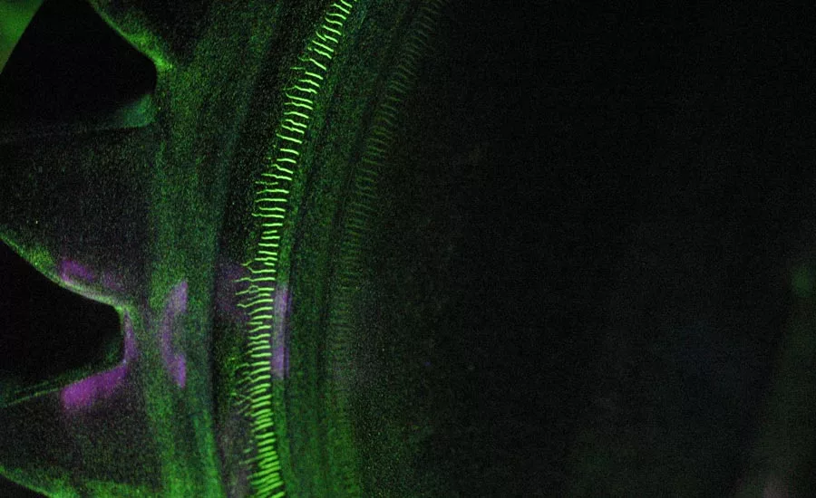
Figure 1 – Fluorescent Grinding Crack Indications.
Toward the end of this decade, our industry will realize a full century since the inception of the magnetic particle inspection method. Since that discovery by Alfred Victor de Forest in 1928, this methodology has been the inspection of choice for production and in-service surface and near-surface discontinuity detection for nearly every form of ferromagnetic component. It has been adopted across the petrochemical, marine, railway, automotive, and aerospace industries as a relatively quick, inexpensive, and accurate evaluation to assure product integrity. Unbeknownst to the average person, this inspection method has been used to assure the quality of their automobile engine/drivetrain, motorboat/aircraft engine, rail car/track, firearm, or building structural weldment. Figure 1 illustrates multiple grinding crack indications on an aircraft gear using fluorescent magnetic particle testing.
As this anniversary approaches, it is helpful to evaluate the recent developments of this important technology. These improvements include the materials used in the process, the equipment used to magnetize the test subjects, the methodology to determine adequate magnetic flux density as well as the lamps used to illuminate fluorescent magnetic particle indications.
Concerning materials, not much has changed for the magnetic particles themselves. However, for wet applications, certain suppliers provide more benign carriers that avert the skin sensitivity that many inspectors have to contact with a popular particle carrier. When it comes to the equipment that facilitates the magnetization of the component, there have been significant improvements.
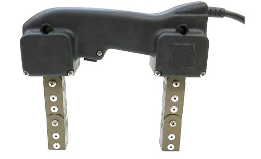
Figure 2 – Dual-Coil MPI Yoke. Source: Parker Research Corp.
For portable applications, the handheld electromagnetic yoke supplies a high intensity, unidirectional magnetization field between the poles when placed on a magnetic part and energized. While magnetic yokes have been used by our industry for quite some time, the manufacturers continue to respond with design improvements such as smaller light-weight yokes that reduce strain on the operator. One manufacturer now distributes a dual-coil model, having the coils located at the upper portion of each leg (see Figure 2). This feature allows a smaller handle, providing a more ergonomic grip as well as reducing the heat within the yoke that is naturally generated with consistent use. Another new model is ideal to use in areas of high moisture and offers improved operator safety. The external push button switch magnetically activates the power circuit from the outside. There is no electrical contact between the switch and internal circuit. Another manufacturer provides a yoke model that features a replaceable cord and a convenient LED light that illuminates the inspection area while the current is on.
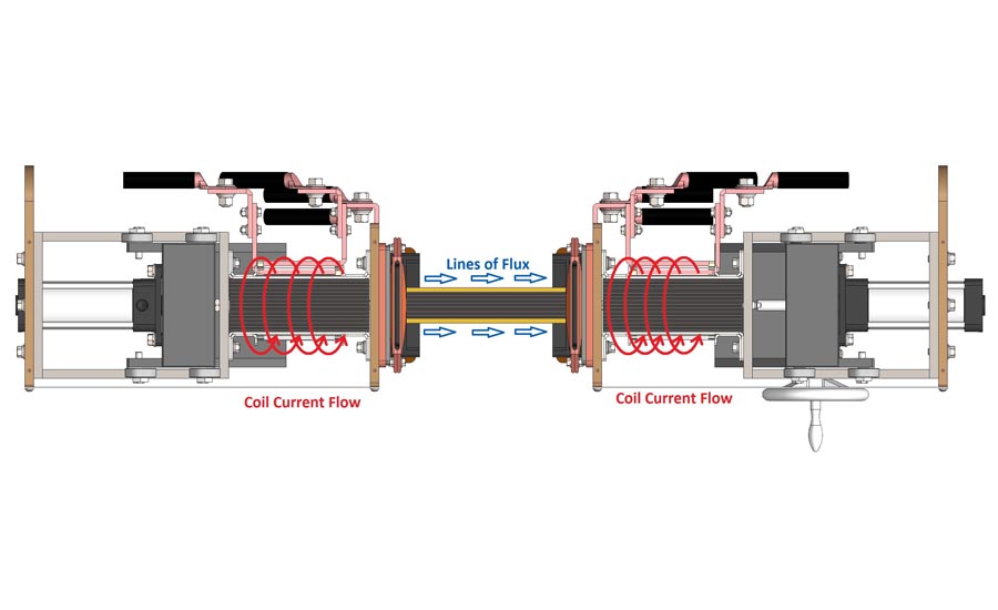
Figure 3 – Top View of Multi-Directional Bench Unit Configuration. Source: Magwerks Corp.
For stationary bench units, the most recent developments have been in the circuitry that converts the incoming high voltage/low amperage electrical current into a low voltage/high amperage output. The accuracy and repeatability of the resultant amperage has been a long standing problem since during the normal machine operation, the copper bus work, secondary cables and electrical current shunt change temperature based upon the amount of power being delivered through the circuit, resulting in a significant resistance change. Two of the major suppliers of these units are now offering circuitry to compensate for these changes due to equipment temperature fluctuations. Regardless of which waveform, one manufacturer now provides an accuracy within 10 to 20 amps when the selected amperage is less than 1000 amps and within 20 to 50 amps when the selected amperage is over 1000 amps. Another manufacturer provides stationary equipment that regardless of waveform, delivers amperage that is accurate +/- 5 amps when selecting an amperage less than 250 amps and no greater deviation of 1% when selecting an amperage greater than 250 amps. What this means in practice for example, is that if an amperage of 100 is selected, the delivered amperage will be between 95 and 105 amps. This same manufacturer provides a unit capable of a high range of 6000 amps while being able to accurately deliver an amperage as low as 5 amps. This low-end capability is uniquely facilitated by metering that provides a 1 amp resolution at this low range.
Another relatively recent improvement is the availability of multi-directional bench units (see Figure 3). These units apply magnetizing current to the headstocks and coils alternately in rapid succession. For users that inspect high volumes of the same part number, automobile suppliers for instance, these units can significantly reduce processing times. In the setup of such an operation, AS5371 shims are normally used to verify an equal magnetizing strength originating from both the headstocks and the coil(s). Thus, a complete magnetization may be accomplished in as few as one magnetizing sequence.
It is an established fact that the magnetic particle method suffers from geometric limitations; that is, not all part configurations lend themselves to 100% inspection. Figure 4 illustrates just such a part that is not easily magnetized in two directions as required by most process specifications. Since electrical current takes the path of least resistance, performing a direct headshot on this part will not adequately magnetize the three crosspieces in the middle of the component.
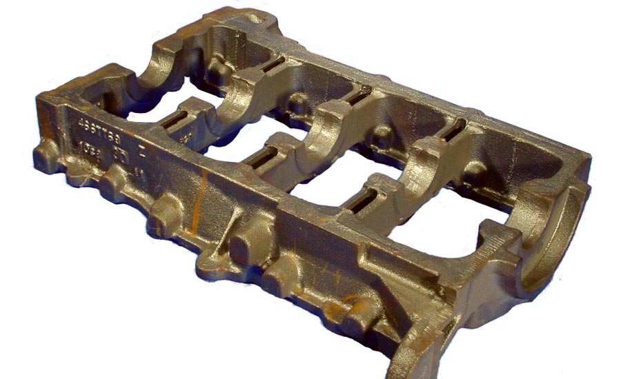
Figure 4 – Engine Bed Plate. Source: Magwerks Corp.
However, having a multi-directional unit with the two coils as shown in Figure 3 provides an additional capability to inspect odd shaped parts. The two coils are normally wired “aiding” in a North-South/North-South configuration. However, changing the wiring order of the coils to North-South/South-North produces a “bucking field,” wherein the coil produce opposing magnetic fields. Because of the grid-like structure of the part, a bucking field produced more uniform results throughout the part versus the standard single polarity coil field.
Another common process limitation is inducing a longitudinal magnetic field in parts with a small length-to-diameter ratio such as a ring-shaped part (see Figure 5). By using a prefabricated “toroidal bar” and a time-varying magnetizing waveform such as AC or HWDC moving through the primary coil, this results in a secondary current flow around the ring producing a toroidal magnetic field that will produce flux leakage around any circumferential discontinuity in the ring. Bearing manufacturers would use a variation of this toroidal fixture in a multi-directional table-top configuration to inspect bearing rings having a very smooth surface in a non-contact manner.
Perhaps the recent addition of LED UV lamps to our magnetic particle testing repertoire has had the most direct impact upon the inspection process. These lamps, whose manufacturing is governed by specification ASTM E3022, have been wholeheartedly accepted by the practitioner for a variety of reasons. First, they do not generate the heat, typically 180 F, that a conventional mercury vapor lamp would produce. Not only is this heat unwelcome in the typical inspection booth, but such lamps have accidentally burned innumerable inspectors. Also, it is a rare veteran magnetic particle inspector who has not unintentionally touched the mercury vapor lamp to the coil during the magnetization process, resulting in the lamp being extinguished. However, LED UV lamps do not suffer from this limitation as they are not affected by the strong external magnetic field generated by the coil. Another advantage of the LED UV lamp is the instantaneous output. Whereas the old-style mercury vapor lamps had to “warm up” for several minutes before an adequate illumination level was reached, the LED UV lamp starts out at a higher level and then “stabilize” to a slightly lower output. But the typical illumination value that LED lamps provide is the primary advantage of this lamp. As the majority of inspectors would attest to, the brighter the lamp is, the easier it is to detect the potential discontinuity.
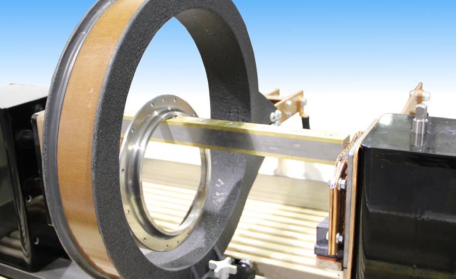
Figure 5 – Ring Shaped Part with Toroidal Bar Coil Magnetization. Source: Magwerks Corp.
On the other hand, this high intensity illumination can lead to the condition termed “veiling glare,” a condition caused by highly finished test piece surfaces reflecting the UV back into the inspector’s eyes, reducing the inspector’s ability to distinguish the contrast between the background and the fluorescent indication. This condition can be averted by wearing UV blocking glasses, whether they be safety glasses or amber tinted glasses available from NDT supply houses. Some prime manufacturers limit the maximum output of UV from the lamps due to potential particle fluorescent pigment fade due to prolonged exposure, but such concerns can be easily addressed by only illuminating the test subject during the actual inspection of the magnetized part after particle application.
Finally, the specifications that undergird the magnetic particle inspection process are being continually updated to keep abreast of technology improvements while maintaining industry best practices. Since utilizing AS5371 QQI shims or the Hall Effect gaussmeter have proven far superior to rule-of-thumb empirical formulas that have been used for decades to determine adequate magnetization, many industry specifications have been prohibiting the use of such formulas. While the magnetic particle inspection method is almost 100 years old, the process is well situated to maintain its position as the superior inspection process of choice for ferromagnetic components.
Looking for a reprint of this article?
From high-res PDFs to custom plaques, order your copy today!


