Ultrasonic Techniques for High Temperature Hydrogen Attack
Well-trained NDT technicians using the right combination of ultrasonic techniques can improve plant reliability and worker safety.
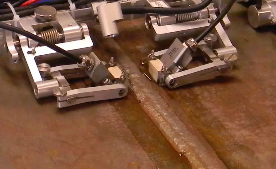
The scanning device required to support the simultaneous encoded application of PAUT and TOFD needs to support four search units. Source: Zetec
It’s been nine years since a heat exchanger burst at an oil refinery in Anacortes, WA, fatally injuring seven workers and bringing renewed attention to the risks of high-temperature hydrogen attack (HTHA).
The U.S. Chemical Safety Board determined that HTHA caused one of six carbon steel pressure vessels in the refinery’s naphtha hydrotreater unit to weaken and rupture, leaking a mixture of hydrogen and raw naphtha into the air. The gas combusted almost immediately, producing an explosion and fire that burned for more than three hours.
While many factors contributed to the incident, the physical cause of the rupture could be traced back nearly 40 years to when the heat exchangers were built and put into service.
The broken pressure vessel that surrounded the heat exchanger consisted of a series of four steel sections or “cans” welded to form a cylinder. Construction required a longitudinal weld to make each can and three circumferential welds to join the four sections end to end—procedures that resulted in significant heat-affected zones (HAZ). The choice of material for this particular vessel was carbon steel (SA-515-70), since the expected operating temperatures and pressures were thought to be below the American Petroleum Institute’s standard at the time for determining the potential for HTHA.
In carbon steel, HTHA can occur when the metal is exposed to hydrogen at a temperature generally above 205 C (400 F) and at high pressure. In this environment, hydrogen can dissociate and react with carbides in the steel to form methane. Methane molecules build up in the grain boundaries, where, over time, they can lead to surface decarburization, microcracks, and eventually large fractures. According to the CSB report on the oil refinery incident, investigators found a crack in the failed pressure vessel that was 48 inches long and more than one half of an inch deep.
ULTRASONIC TECHNIQUES
HTHA can occur in refineries, petrochemical plants, hydrogenation plants, and other facilities where hydrogen-containing fluids are processed at elevated temperatures and pressures.
The early stages of HTHA can be hard to detect with ultrasonic testing methods because the methane voids are typically smaller than 0.1 mm (0.004 inches), and therefore much smaller than the typically applied ultrasonic wavelengths.
For this reason, a combination of advanced ultrasonic techniques—specifically time of flight diffraction (TOFD) and standard phased-array and high-resolution TFM (total focusing method)—is necessary. Let’s look at the advantages of TOFD and TFM for early detection and better characterization of HTHA.
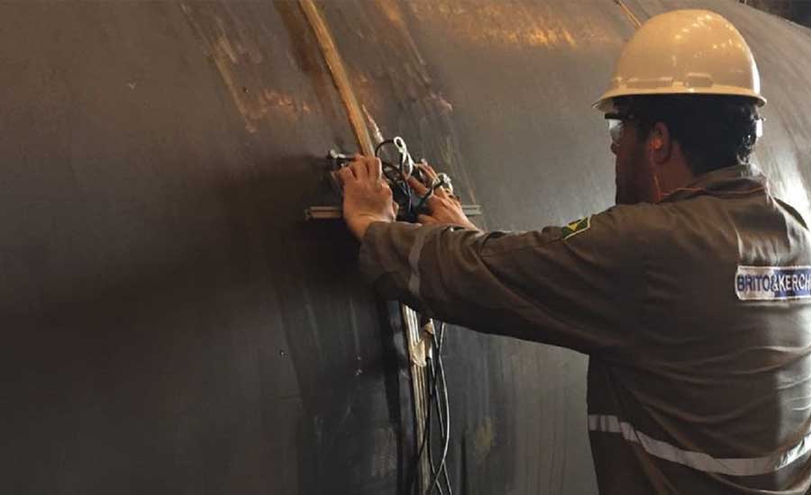
The early stages of HTHA can be hard to detect with ultrasonic testing methods because the methane voids are smaller than the typically applied ultrasonic wavelengths. Source: Brito & Kerche
TOFD
Time-of-flight diffraction is a rapid and robust ultrasonic technique for initial screenings of base material and welded regions.
In a TOFD system, ultrasonic probes are situated on opposite sides of a weld. One probe acts a transmitter, emitting an ultrasonic pulse into the material, the other functions as a receiver.
Instead of measuring only for the high amplitude sound waves that reflect off the back of a component, TOFD calculates the response time of low-amplitude waves that are diffracted by the tips of discontinuities.
The simultaneous use of phased array UT and TOFD can detect all welding flaw types and provide reliable through-wall sizing in one inspection. The inspector can use a two-sided phased array UT examination with standard shear-wave phased array probes to detect planar and surface-breaking flaws, while the TOFD technique can accurately locate and size embedded flaws.
Because TOFD has a high degree of repeatability, changes in degradation can be recorded and compared over time. Using phased array UT and TOFD together can also increase the productivity of the inspection crew simply by reducing the number of scans and manipulations that need to be done.
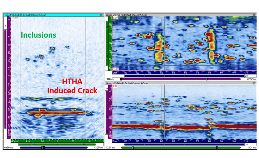
Increased grain noise (short indications) and clustering (beehive) in A-Scan signals are indicative of early-stage HTHA. Source: Lavender International
A similar technique using TULA probes (TOFD Ultra Low Angle) is well suited for inspections of thicker base materials. Like regular TOFD, increased grain noise (short indications) and clustering (beehive) in A-Scan signals are indicative of early-stage HTHA.
At a minimum, the scanning device required to support the simultaneous encoded application of PAUT and TOFD needs to support four search units (two phased array UT probes and one TOFD pair).
However, as the thickness of the material becomes greater, the TOFD inspection needs to be done in different depth zones and therefore requires more TOFD probes and larger probe-center separation to cover the full volume of interest.
In order to maximize the efficiency of the inspection crew, which often has to inspect thin-wall and heavy-wall components in the same shift, the scanner should allow the flexibility to support a wide range of thicknesses.
TFM
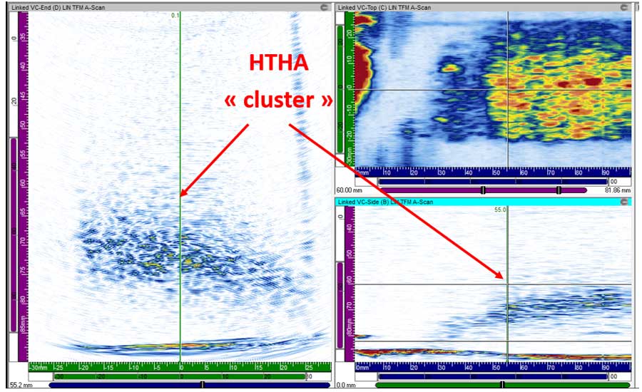
Combining TOFD with high-resolution “live” TFM leverages the benefits of both techniques for HTHA inspections.
The TFM algorithm sums the elementary A-Scan signals from all elements in the array to generate a frame of pixels, where each pixel is computed using a dedicated focal law. TFM frames can be used for “live” interpretation or they can be stored for each position of the probe, very similar to a “dynamic” merge view in regular phased array.
In theory, ideal focusing is achieved in each point of the frame, but the focusing capability of this technique still depends on the acoustic wavelength and total aperture of the array.
Therefore, some conditions must be met to effectively obtain ideal focusing.
For example, TFM has the capability to conserve ideal focusing over a much larger region as long as the region of interest is in the near-field of the active aperture.
For thicker components, a large aperture is required both in standard phased array and TFM to be able to focus in the complete region of interest. In other cases, for thinner components, a large active aperture is not always required. For instance, to perform corrosion inspection on components between 5 and 15-mm thick, it can even be an advantage to use a smaller aperture to generate the TFM frames. In these thin components, only the probe elements close to the defects will adequately contribute to the imaging.
It’s useful to have a phased-array UT instrument with the capability to perform a “sliding” TFM with a partial aperture of the probe—for instance, 16 or 24 elements out of 64. This sliding TFM is the equivalent of the electronic linear scan, but the moving aperture is used to generate a totally focused signal. It can also reduce the wedge echoes when performing TFM with the probe on a 0-degree LW wedge. These wedge echoes can generate the typical “arcs” at the edges of the TFM frame and reduce the quality of the image.
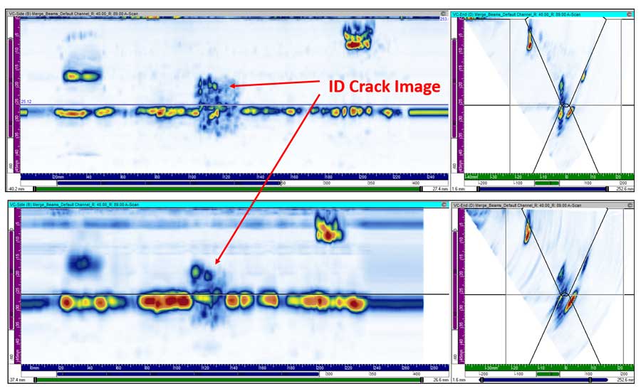
As with any weld inspection with phased array, it’s important to position the probes at the optimal beam angles for detecting the typical welding defects. OD cracks would be insonified with a 45-degree angle after skip; lack-of-fusion defects with 60 degrees after skip; and ID cracks or incomplete penetration with high angles in the first half skip.
It’s important to remember that the TFM technique doesn’t use real angle beams: it uses the capability of each individual element of the probe to insonify the defects and receive useful responses. This means there will be contributions from a wider range of angles, but we still want to benefit from the optimal sound paths.
In the majority of configurations, the optimal probe position for standard phased array will also work perfectly for TFM.
CONCLUSION
There have been a number of changes to regulations and industry guidance to reduce the risk of HTHA, including post weld heat treatment (PWHT) and recommendations from the CSB to replace carbon steel process equipment that operates above 205 C and greater than 50 Pisa hydrogen partial pressure.
However, HTHA remains one of the more challenging inspections across a wide range of industries. Well-trained NDT technicians using the right combination of ultrasonic techniques and advanced technology can do their part to detect and monitor HTHA damage while improving plant reliability and worker safety.
Looking for a reprint of this article?
From high-res PDFs to custom plaques, order your copy today!


