NDT in Aerospace
Automated Eddy Current Testing Solution for Aero-engine Discs
Eddy current testing is a crucial part of quality control.

Figure 1. Automated Eddy Current Scanner with 3D Scanning Capablities
Aero-engine discs are very critical parts since they are exposed to high stress and temperature during flights. Engine disc components such as bearing rings, fan and compressor discs are subjected to extensive inspections during the different manufacturing stages, including dimensional controls up to the detection of the tiniest surface flaws on rolling surfaces (bearing raceways). The forging process, with which most of these parts are formed, is a high energy process that can result in many different types of defects, some of these being near surface or surface breaking cracks. Thus, complementary NDT technologies such as ultrasonic, liquid penetrant and eddy current testing are commonly used for flaw detection on those components. However, as the shapes and materials of these parts become more and more complex, automated inspection plays a crucial role in ensuring that these parts are defect free. To overcome the above-mentioned challenges, this article demonstrates an automated eddy current solution with 3D scanning capabilities developed to inspect aero-engine forged discs.
Automated Eddy Current Testing
Eddy current testing technique plays an important role in quality control of aero-engine components. When inspecting with automated eddy current scanners, surface as well as some sub-surface flaws are detected by scanning the surface of the inspected material. Such scanners are usually Cartesian scanners built with rotational axes and designed to perform high speed and repeatable nondestructive testing. However, forged discs have complex shapes with multiple surface transitions that make it difficult for simple 2-axis and rotational scanners to perform inspections of these parts. In order to achieve the desired inspection results under these circumstances, automated eddy current solution with advanced 3D capabilities needs to be used to perform full scans on aero-engine discs. Tridimensional inspection of these discs is best achieved using computer-aided design (CAD) files to perform accurate inspection in the 3D space.
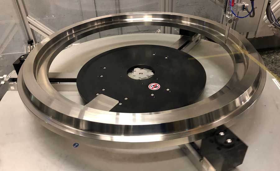
FIGURE 2: Turntable with centering mechanism
3D Eddy Current Testing
To overcome the above-mentioned part geometry and inspection challenges, an automated eddy current testing solution with 3D scanning capabilities is proposed. The developed solution is engineered around a mechanical scanner, an eddy current instrument, a turntable and a relatively small, high frequency eddy-current coil that is scanned across a selected or the whole disc surface. During scans, the turntable rotates the engine disc, while the probe is being moved in the 3D space while maintaining constant lift-off and perpendicularity with the tested surface until the automated inspection is finished. Turntable rotation speed is continuously adjusted to maintain a constant linear scanning speed on the surface and based on the radial position of the probe on the surface. This is essential to maintain correlation between the signal obtained during the scan and the signal obtained during the calibration phase on one or multiple reference notches. During this operation, the system records the eddy current signals and the associated scan positions for C-scan analysis and reporting.
The mechanical scanner axes (Z, Y, Gimbal and Turntable) as well as the turntable centering mechanism are all highly accurate and repeatable and this allows for advanced features such as return on defect, constant linear inspection speeds, inspection and surface following at the optimized probe squint angle, and other features. The gimbal axis is designed to absorb vibrations and is equipped with two encoders that monitor angular as well as probe lift-off position, ensuring that the eddy current signal is constant throughout the entire inspection.
The system also integrates a support for calibration standards, allowing the operator to adjust the instrument sensitivity by running automated scans on the standard section, without having to remove the part under inspection, which is particularly useful if sensitivity has to be verified while scanning a part.
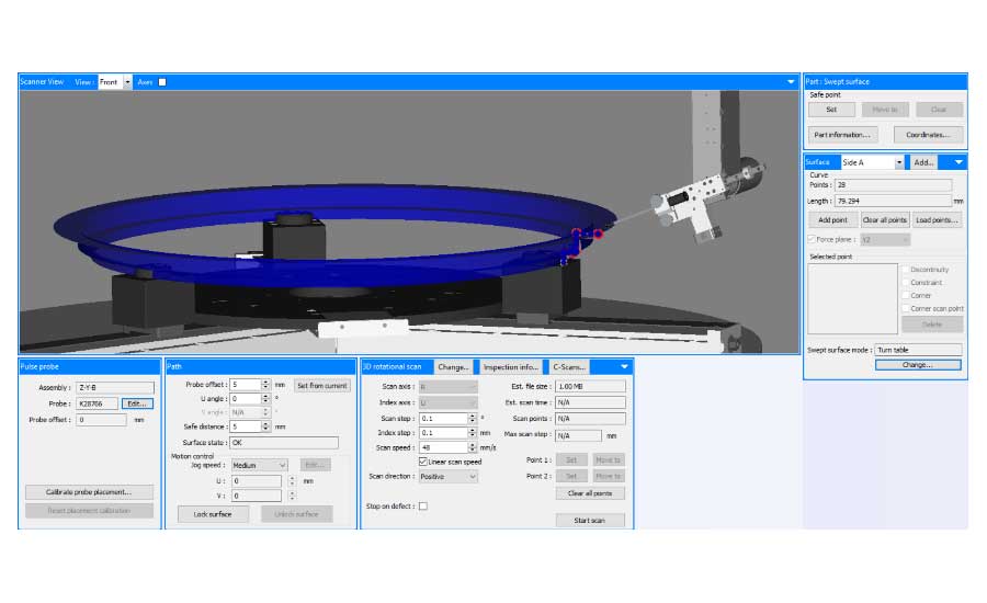
FIGURE 3: This software allows users to easily load and unload the CAD files created for scanning geometries
Advanced tools and algorithms are also integrated in the software (TecViewTM EC) for part programming, importing the 3D CAD drawings of the part, generating the scanning trajectories and completing the motion-controlled inspection scans. The software allows the user to carry out complex scans with real-time signal processing, imaging and scanning repeatability. To increase the system’s flexibility, part geometry can be thought using the handheld pendant or from an imported CAD file. In both cases the part profile can be saved and recalled.
The software also enables users to create inspection zones and up to eight frequency channels in a single scan inspection. The outcoming results can be easily analyzed and interpreted in the software analysis module; defect sizing tools, signal-to-noise measurement tools, automatic threshold and area-based defect sorting are a set of interactive tools that can be easily used to quantify the detected indications.
Inspection Results of Pre-machined Discs
The example presented below demonstrates how 3D scanning solution and automated eddy current testing are being used to perform inspections of pre-machined discs. The first figure shows C-scan results of a calibration sample with calibrated flaws. The C-scan result represents a color-coded 3D presentation of the data collected during the automated inspection of the disc. The red spots on the C-scans represent the detected flaws.
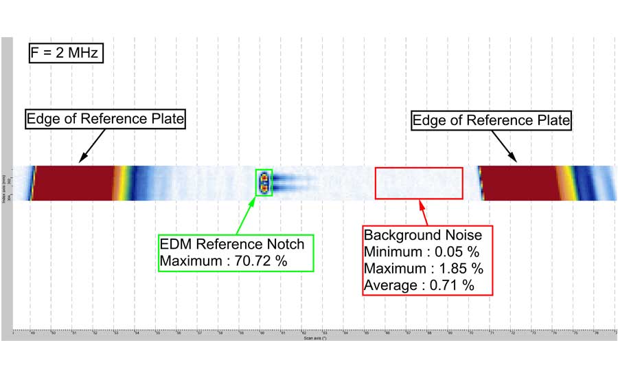
FIGURE 4: Example of response from a reference standard with EDM notch and related analysis
Optimization of the instrument sensitivity can be quickly achieved on multiple frequencies by individually adjusting the signal phase angle and gain for each recorded frequency in the analysis starting from a first scan of the sample. As illustrated in figure 4, the use of detection boxed directly on the C-Scan image allows users to quickly find the maximal notch response without having to browse through each individual strip chart.
With the ability to scan multiple surfaces of the disc with the 3D scanning possibilities, a C-Scan representing the indications mapped on the geometry of the scanned part can be obtained, aiding in the interpretation and identification of flaws.
By optimizing the probe squint angle, maintaining constant probe lift-off, as well as achieving an accurate motion control of the probe, a very high signal-to-noise ratio can be achieved, thus allowing for detection of very small flaws. The example below shows real surface cracking validated by liquid penetrant testing and detected by eddy current at a signal level 10 times lower than the EDM notch level.
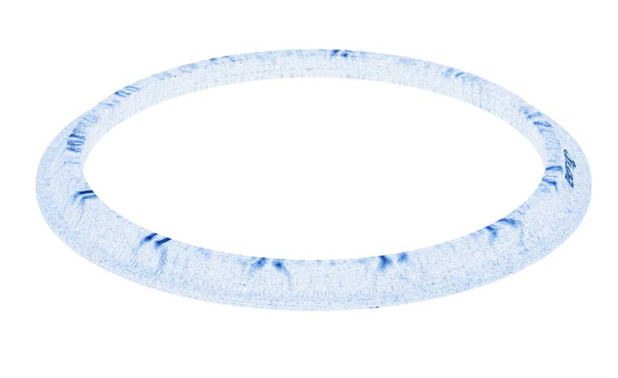
FIGURE 5: C-Scan mapped on the 3D representation of a disc
Conclusions
This solution allows for 3D inspection of complex aero-engine discs at multiple frequencies in a single pass. Such automated solutions will enable manufacturers to ensure the quality of their parts while allowing them a high throughput. By performing an optimized and well controlled 3D contour following of the eddy current coil at constant surface speed, the entire surface of discs can be scanned at high signal-to-noise ratios. With a simple change of the automated probe support, the system can even be used for the inspection of machined aero-engine discs. The development of 3D tools for automated eddy current testing can help ensure that a full inspection is the most optimal way.
Looking for a reprint of this article?
From high-res PDFs to custom plaques, order your copy today!


