NDT | Eddy Current
Advanced Eddy Current Scanning Solution for Aero Engine High Pressure Compressor Rotor Spools
The inspection challenge in such situations consists of automating the inspection process.

Figure 1. Illustration of an aero engine and a High Pressure Compressor Rotor Spool (HPCR) All Images Source: TecScan Systems Inc.
Aircraft engine MRO (Maintenance, Repair, and Overhaul) plays a crucial role in maintaining engine continuous operation and flight safety. The high-pressure compressor rotors (HPCR) section of the engine is among the components that require periodic inspections to detect the tiniest manufacturing flaws as well as any crack produced by the loads, fatigue or temperature variations encountered in flights. The HPCR spool section consists of multiple spool stages, where the hub-to-web transitions and the web areas are required to be inspected for any surface defects or cracks that could occur during operation or at the manufacturing stage. The inspection challenge in such situations consists of automating the inspection process, which require reaching inside the HPCR spool through either ends of the rotator spool to inspect the targeted web and hubs-to-webs transition areas; those are closed spaces with little room to fit a probe manipulator, as well as being nonvisible to the operator.
To meet these requirements and overcome the complex geometrical obstacles of the HPCR spool, an advanced eddy current scanning solution and 3D modeling tools were developed and tested using high pressure compressor spool samples with simulated crack like defects. This also included the development and implementation of the eddy current inspection technique for some pre-selected stages in the compressor rotator spool.
Advanced Eddy Current Scanning Solution
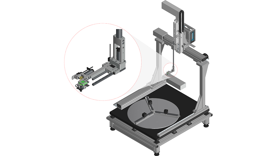
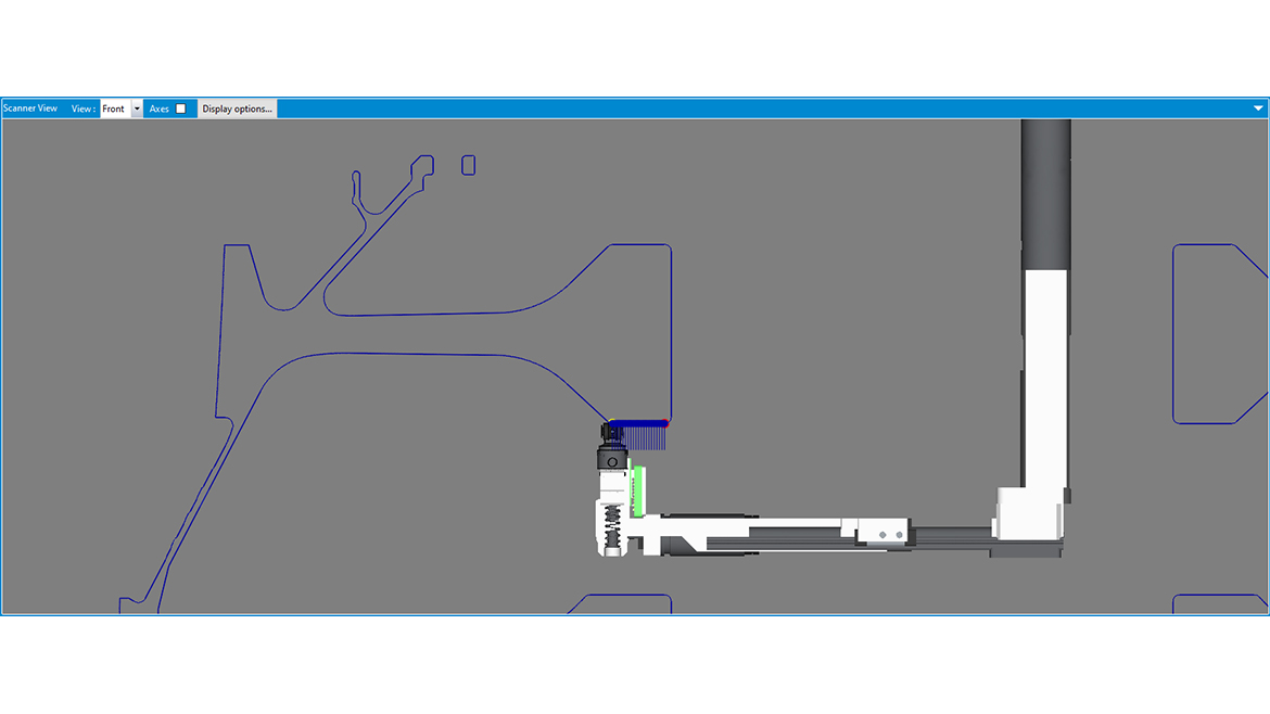
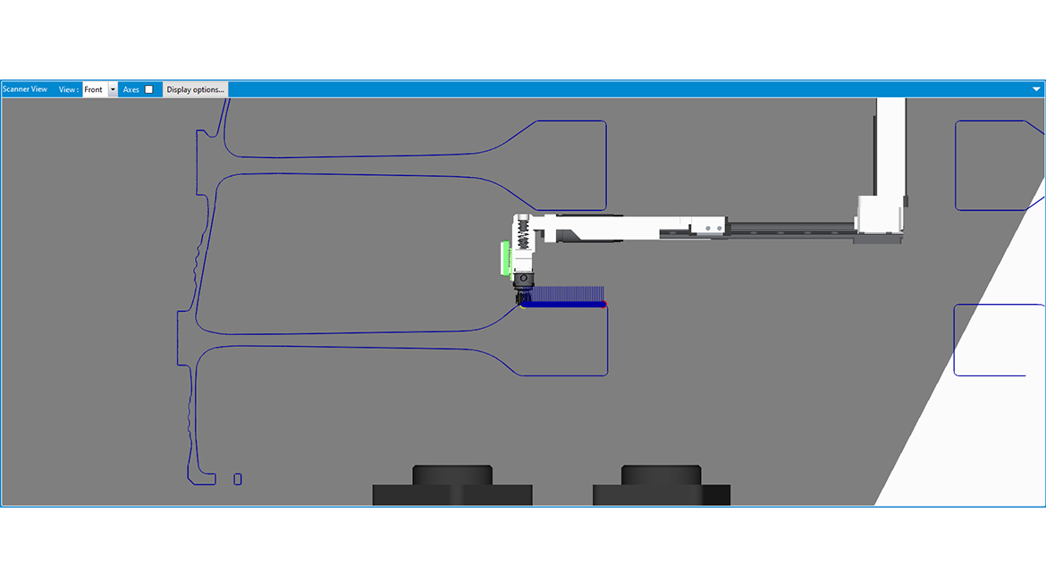
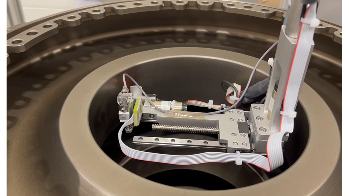
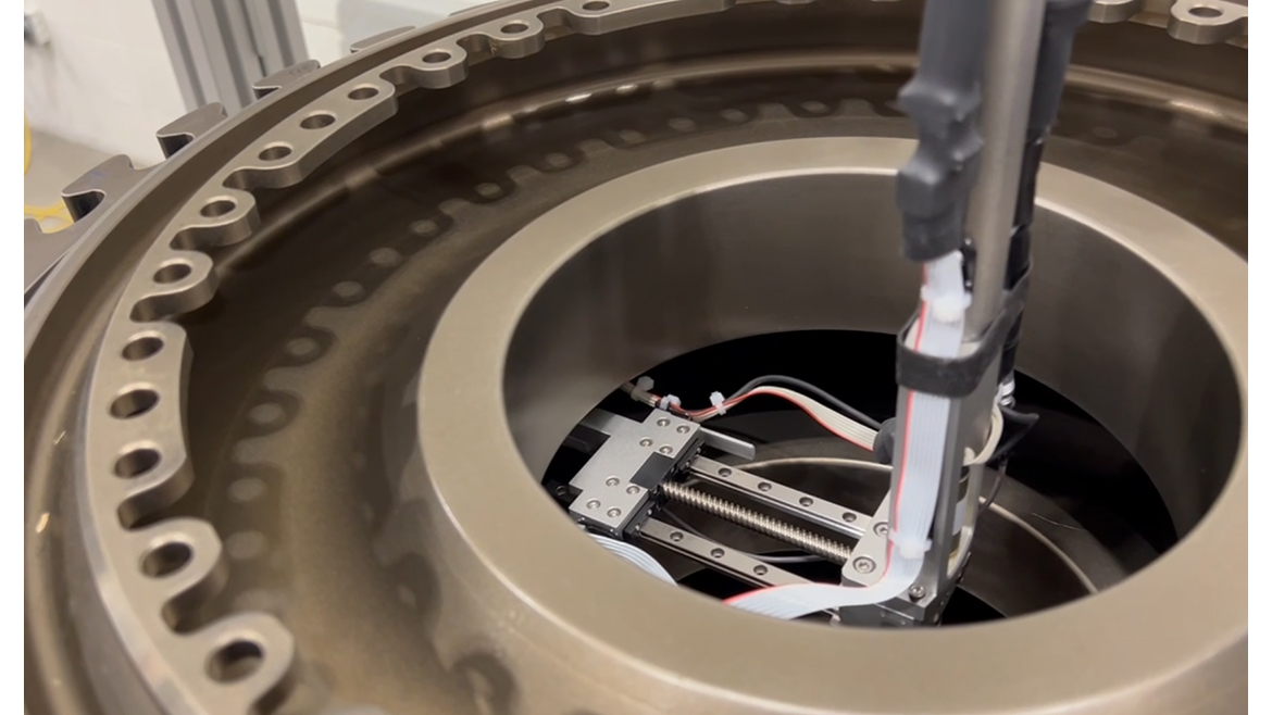
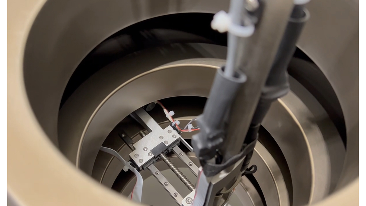
The developed eddy current scanning solution consists of a mechanical scanner with X, Y, Z and Turntable axes, as well as a Telescopic Gimbal attached to the Z axis, which is specifically designed to enter the spool from the central bore and scan inside the tight HPCR spool areas. The Gimbal is designed to automatically extend and reach the targeted inspection areas inside the spool section as seen in the following figure. A compact gimbal rotation axis is located at the end of the telescopic arm to control the coil orientation. The Telescopic Gimbal axis is also designed to absorb vibrations and is equipped with encoders to monitor the axes displacement, as well as to confirm and control the probe position as it contacts the part, thus ensuring that the eddy current signal is constant throughout the entire inspection process. The tip of the gimbal assembly is designed to hold the eddy-current coil and to scan the selected spool sections. A calibration standard is also integrated to the scanner to allow the operator to calibrate the eddy current instrument sensitivity without removing the inspected High Pressure Spool.
Modeling Of Scanning Components
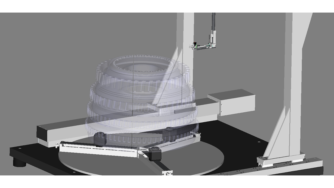
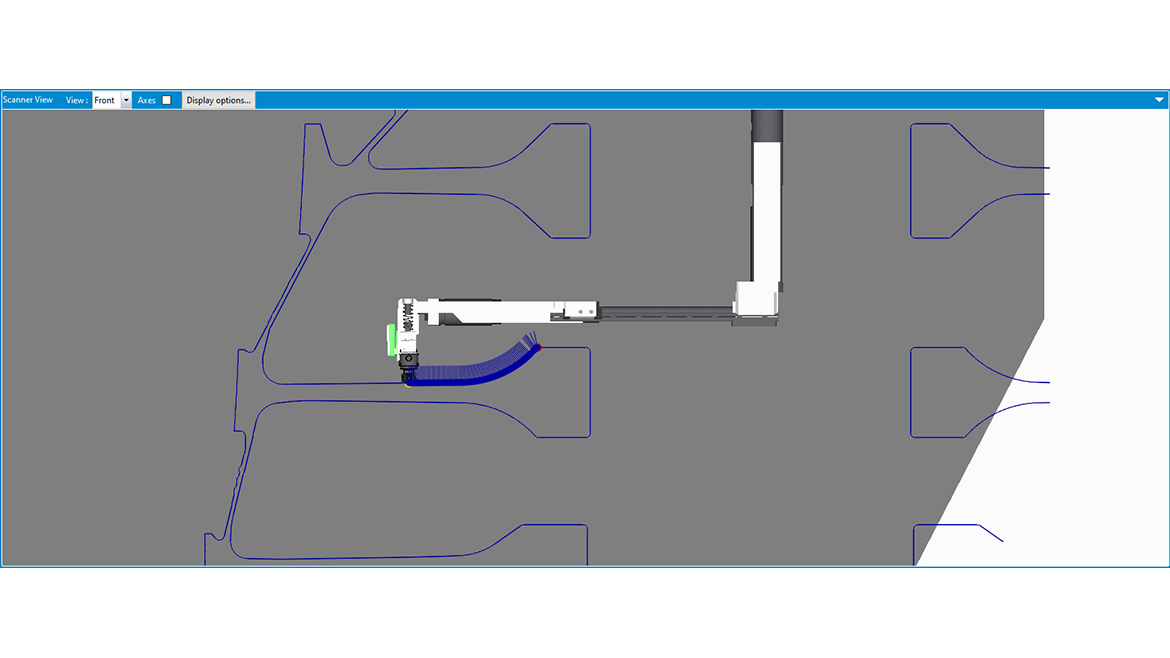
Manually accessing the areas between the spool stages is unfeasible due to the impossibility to have a clear view of the internal spool structure from outside. To optimize the inspection accuracy and the overall eddy current inspection solution, the 3D geometry of the HPCR spool was converted from a CAD file and imported in the inspection software environment. The geometry of the eddy current scanner along with the Telescopic Gimbal were also modeled and imported in the software; accurately displaying the part within the scanner’s environment allows the user to properly import or generate all the necessary scanning trajectories in order to complete the scanner displacement and motion-control. Due to the limited space inside the spool, displacements of the gimbal must also be programmed to safely enter the part and navigate between the spool stages without colliding with the part.
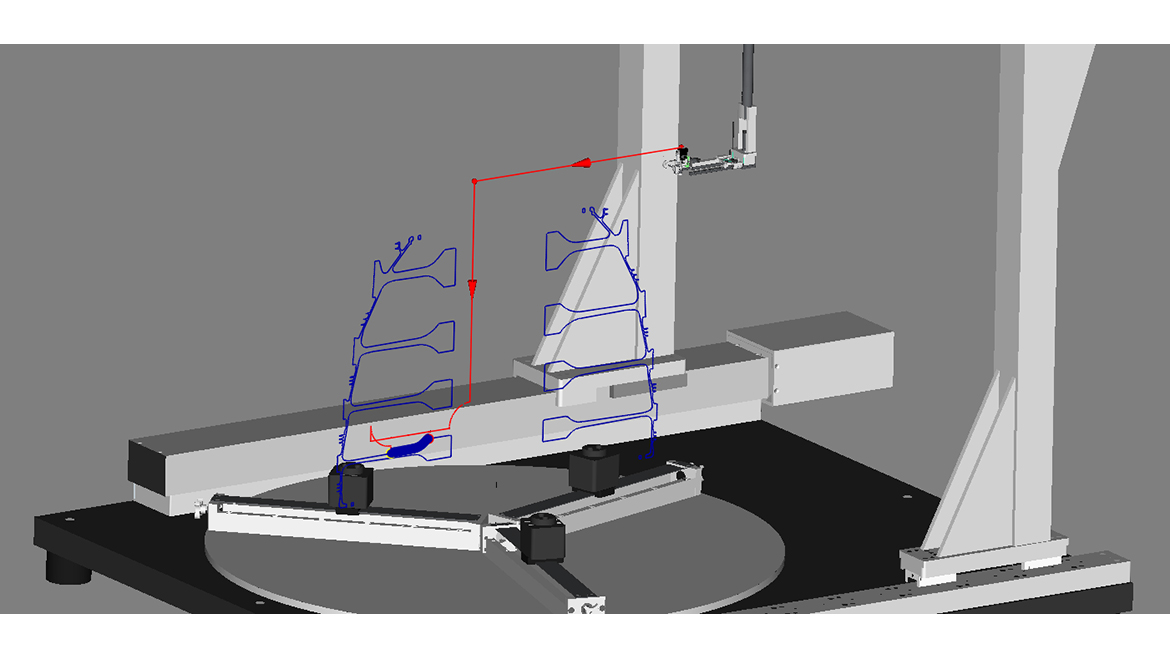
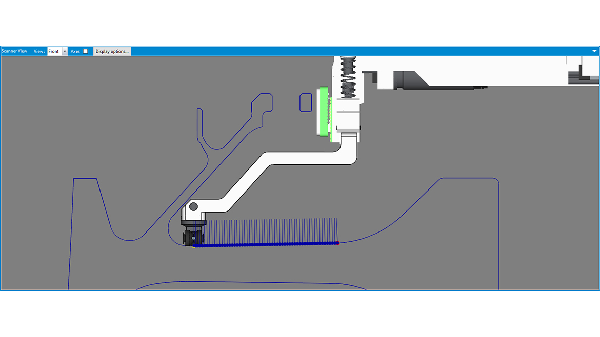
Once the models are imported in the software, an important step needs to be taken in order to validate the scanner and the Telescopic Gimbal axis displacements before starting the inspection process. A simulation mode can be activated to virtually navigate the probe and gimbal assembly within the spool and define a safe trajectory to enter the part, to move from one stage to another, and to exit the part safely. This tool, when combined with a precise modeling of the scanner, represents a valuable asset that helps the operator to program and validate collision free movements within the spool structure. Once this validation is completed, the generated trajectories can be used to move the scanner along the inspection surface without risks of any collision while inside the spool sample. These trajectories can then be saved as part of the scan programs and recalled for other parts.
Scan Results
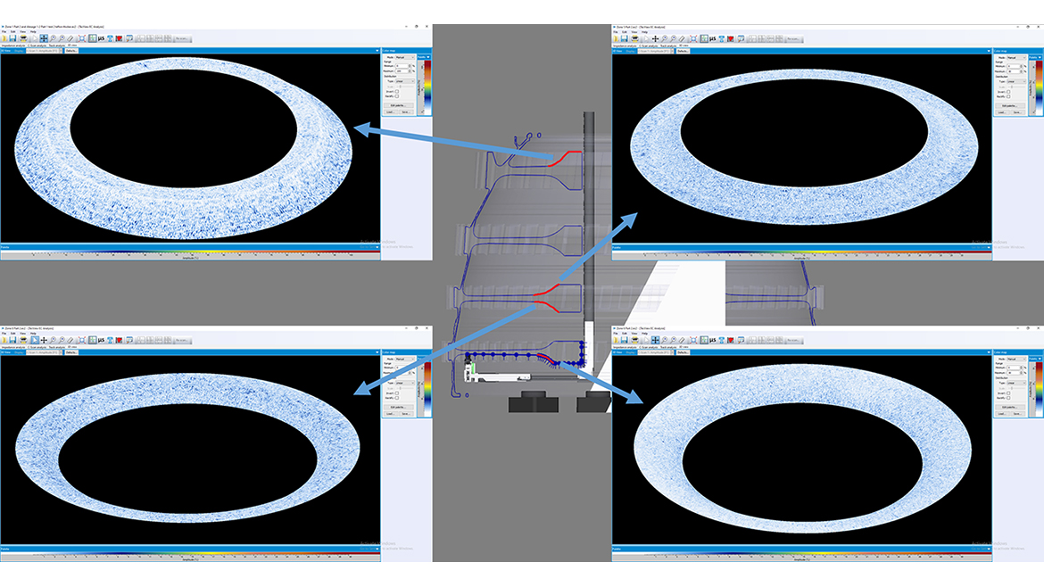
Automated inspection tests were performed on different sections of a high-pressure compressor spool sample. A small Teflon tape was attached to the part surface on one of the hub-to-web transitions to validate proper probe contact and sensitivity. The sample was inspected using a commercially available 2 MHz differential eddy current probe and at a scanning resolution of 0.2 mm. An eddy current instrument was used to drive the coils and convert the eddy current signals to digital format. C-Scan images of the inspection were finally produced in order to provide more intuitive and accurate analysis possibilities in terms of detection, sizing and positioning. The image below shows a C-scan result obtained from the inspection of a hub-to-web transition section of one of the spool stages. While the Teflon tape is not representative of a real flaw, it generates a lift-off signal that confirms proper probe contact with the part across the transition area.
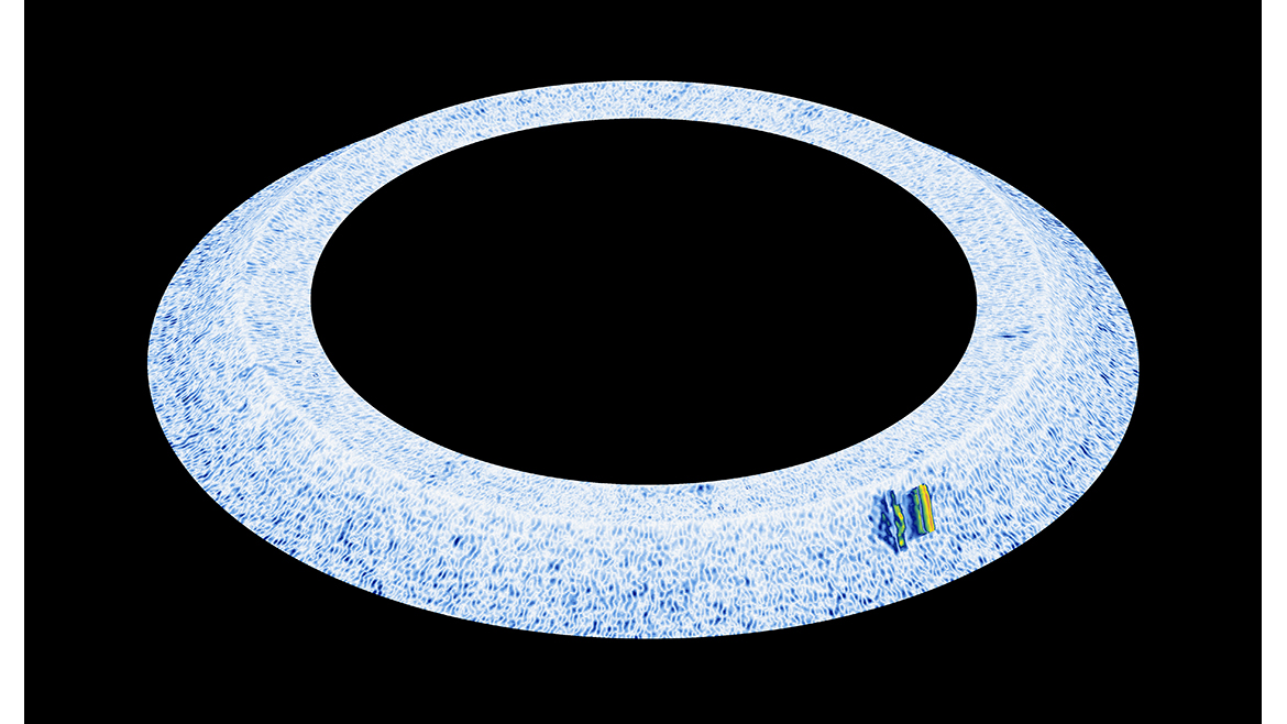
The figure below shows example of C-Scan images obtained at different hub-to-web transition areas based on a calibration of the eddy current instrument on a reference notch, all of them displaying a similar background noise level.
NDT
A Quality Special Section
In conclusion, the eddy current scanning solution that was developed for hard to access HPCR spool areas represents a reliable inspection platform that produced repeatable results. The Telescopic Gimbal with encoded probe position and rotation was successfully tested on a HPCR spool sample. The advanced modeling tools and the ability to import the sample and scanner geometry within the inspection setup proved to be an important tool for the overall automation of the inspection and the minimization of risks of collision during setup. The scanner trajectories were all successfully calculated and validated from simulations for the entire inspection process before the scanning head was physically inserted in the part. By combining 3D modeling tools with an advanced mechanical system, this automated eddy current inspection solution presents all the necessary tools to overcome the complexity of the setup resulting from the part’s geometry and generate the scanning trajectories required to complete inspection scans safely and efficiently.
Looking for a reprint of this article?
From high-res PDFs to custom plaques, order your copy today!


 or manufacturing system")


