NDT | Eddy Current
Conventional Eddy Current transitions to Eddy Current Array
This inspection process is becoming more objective and precise, with greater accuracy and consistency across various industries.
All Images Source: NDT Solutions
Over the years, eddy current testing (ECT) has evolved significantly, driven by advances in technology and changing industry needs. Historically, ECT has been primarily a manual and technician driven process, dependent on the human eye and technician experience to discern differences in the signals produced during the critical inspection. However, with the advent of improved instrumentation and transition to eddy current array probes (ECA), this inspection process is becoming more objective and precise, with greater accuracy and consistency across various industries.
With a focus on the aerospace industry, ECT is one of the most diverse inspection modalities having various techniques for evaluation such as:
- Conductivity measurement, for material variation, chemistry, sampling, and heat damage.
- Conductive and nonconductive material thickness determination for paint and coatings.
- Thickness measurement for corrosion on skins and lap joints.
- High Frequency Eddy Current (HFEC) for surface breaking cracks.
- Low Frequency Eddy Current (LFEC) for sub-surface and multi-layer crack detection.
- Hole inspection with or without threads, prior to and/or after removal of bolt/fastener.
Knowing the capabilities as well as the limitations is essential for an effective evaluation.
- Sensitivity to small cracks, other defects, both surface as well as near surface with detectability decreasing with the depth of penetration within the conductive material.
- Portable equipment, automated and robot applications allow versatility.
- Utilized for more than flaw detection requiring minimum part preparation.
- Conductive material, area of inspection, complexity of specimen is essential for successful examinations.
- Contact and noncontact inspections provide consistent part evaluation.
- Surface finish, roughness, location, orientation, type of flaw as well as configuration may cause false positives requiring reference standards replicating the detectable condition.
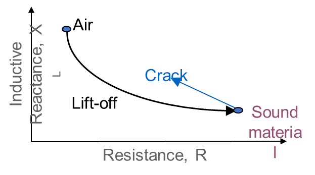
A variety of eddy current instruments are available for use, from simple to complex. These instruments vary in application, flexibility, size, and intuitiveness. Typically, these instruments operate on similar principles. The usability and functionality of the instrument is the most important consideration to the technician who is utilizing this instrument in the performance of their job. Understanding the impedance plane and phase diagram is critical in determining the condition of the material under evaluation as it appears on the screen for interpretation.
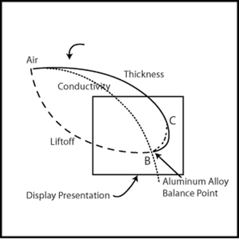
Impedance Plane Diagrams, liftoff, conductivity, thickness and flaw depth
Impedance plane analysis or phase analysis displays the signals generated in an eddy current test are vectors and not scalar quantities. The vectors are defined by two quantities, their amplitude and phase rather than just by their amplitude. Phase analysis of the test signal using a screen display instead of a meter indicating simple amplitude measurements allows a greater level of differentiation between relevant signals and unwanted noise. The impedance plane diagram reacts to the effect of eddy currents on the coil impedance relative to the location on the specimen under evaluation.
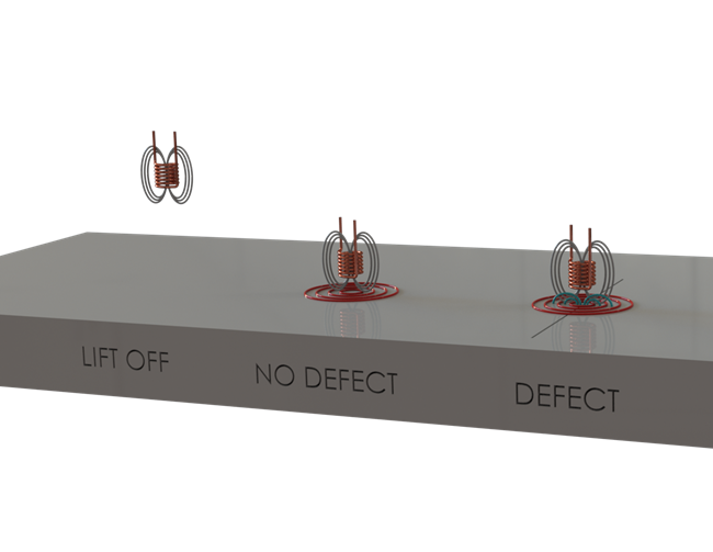
Eddy current equipment utilizes an alternating current (AC) passed through a coil or coils to create an expanding and collapsing magnetic field in and around the coil(s). When positioning the probe onto a conductive material, this changing magnetic field generates the eddy currents within the specimen. Through this interaction of the coil’s magnetic field and the eddy currents, we observe the reactance when measuring changes in frequency, amplitude, sensitivity, impedance, and other characteristics that indicate the presence of a crack, void, or other defects in the test sample.
Equipment factors affect the inspection, such as frequency, amplitude, sensitivity, filtering, phase angle, which make up the “technique” for eddy current test. Material factors require consideration, things that can affect the flow of eddy currents, including the properties of the material or part under evaluation. Technician experience is beneficial in determining all factors when requiring adjustments to the settings or using other techniques to compensate for these effects. Multifrequency instruments offer substantial enhancement of performance by using signals generated by the various frequencies can be “mixed” to prevent display of undesirable signals,
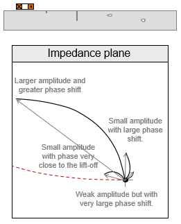
Typical coil placement relative to displayed response
The electrical conductivity of the material being tested or the ease with which electron flows in the material has an effect on the flow of eddy currents it produces, as does magnetic permeability. While the measurement of permeability can be useful in sorting materials, this property can also pose problems. For instance, the so-called “noise” created by changes in permeability when testing ferrous materials makes it difficult to use eddy current testing on carbon steel welds. However, issues may be overcome by using magnetic saturation, multi-frequency inspection, or differential coil arrangements. The noise experienced during testing can often be filtered out, to produce a clearer signal. When a test sample is a part with edge or sharp changes in geometry, there can be what is called an “edge effect” on the eddy currents; placing and balancing the probe near the edge and scanning at that distance can avoid this effect. Similarly, a sample with a complex geometry could create false signals, caused by changes in geometry rather than a defect in the material itself.
Key advances that have improved this versatile inspection are the instrumentation and the manufacturability of the inspection probes. There are different probes for different modes which are available in a variety of shapes, sizes, and configurations. These probes also have different modes of operation, depending on the test coils configuration and how they interface with the test sample.
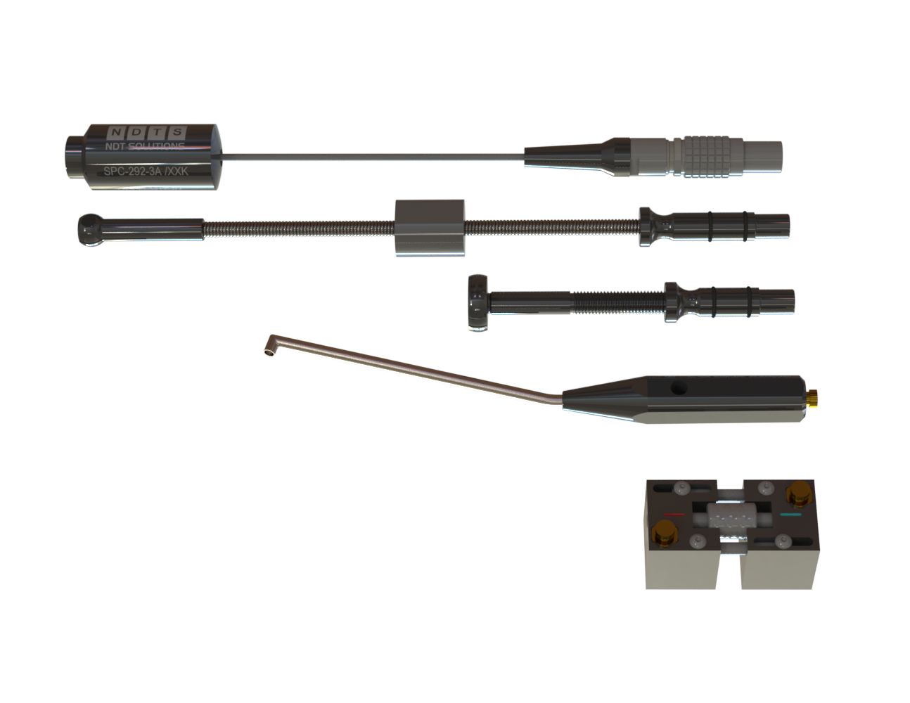
Individual Probes
An absolute probe uses a single coil to generate eddy currents reactive to various changes encountered in the current field and provides a reading from a single point on the test sample. A differential probe uses two coils to provide a basic comparison for detecting flaws, even in materials that may have inconsistencies. Differential signals on a display are a result of one coil over a flaw and the other is over good material. Reflection probes utilize a driver coil and a sensor coil. The arrangement is often differential but may be absolute. The primary advantages of reflection probes are good accuracy (signal-to-noise ratio) and a wide band of operating frequency.
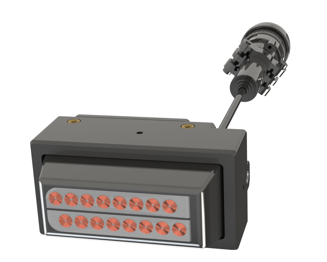
Eddy current array (ECA) is a nondestructive testing technique that provides the ability to electronically drive multiple eddy current coils, positioned incrementally side by side in the same probe assembly. Each individual eddy current coil in the probe produces a signal relative to the phase and amplitude of the structure below it. An array combined with an X/Y scanner creates an image referenced to an encoded position with the location represented graphically as a C-scan image.
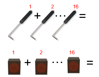
Relationship of ECT single probes relative to an ECA
Most conventional eddy current flaw detection techniques are interchangeable with ECA inspections; however, the advantages of ECA technology allow for improved inspection capabilities and considerable time savings. Eddy current array technology includes the following advantages since ECA is ECT:
- Same depth of penetration
- Same probe configuration available (absolute, reflection, differential.)
- Multiple ECT coils in one probe.
- C-Scan images; allow to show detailed information, post processing of all channels at the same time.
- Scanning in a single-probe pass yields larger areas of data on the aircraft, while maintaining higher resolution.
- Imaging improves flaw detection and sizing.
- Inspection of complex shapes utilizing customized probes matching the profile of the part.
- The smallest defect for detection creates the requirements for the ECA design. Designing the coil type requires knowledge of the defect and the depth for detectability. The positioning of each coil is critical according to the resolution required by the inspection application. The path for scanning defines the number of coils for coverage of the surface area required for the inspection.
Coil sensitivity is not constant over its width or diameter. Maximum signal amplitude is a result when the defect passes the center of the coil. The sensitivity quickly decreases when the defect passes the edge of the coil. Sensitivity will not be uniform over the probe width. Poor resolution, not good for defects smaller than the coil width.
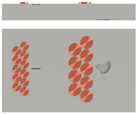
Flaw detection relative to coil design
NDT
A Quality Special Section
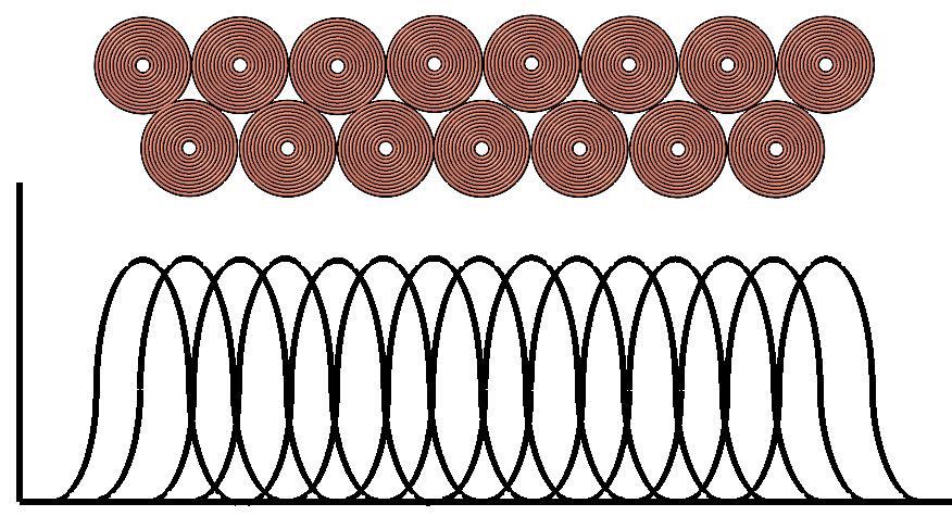
Resolution of an ECA probe resolution improves by using two rows of coils placed side-by-side. Uniform sensitivity over the probe width improves resolution that allows smaller defect detection. When utilizing an absolute bridge array, the design is an Omni Directional probe, good detection for cracks at any angle.
- A double-row probe maintains uniform sensitivity over its width.
- Single-row probe has a nonuniform sensitivity.
- When the crack is parallel to the scan direction and between two coils a reduction of sensitivity is noticeable.
Encoders utilized during scanning align the data in a C-scan documenting the area of coverage for the same number of coils is relative to the condition under evaluation.
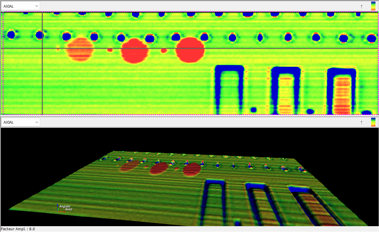
Encoded c-scan and 3D Imaging
Eddy current technology is evolving with improved detection of both surface and subsurface flaws along with defining critical material attributes. This complex analytical tool can store raw data while integrating with scanners or robotics for permanent results. Array technology is being utilized to replace single conventional probes for multiple applications with broader applications, improved cycle times and inspection results.
Looking for a reprint of this article?
From high-res PDFs to custom plaques, order your copy today!


