Knapheide Saves Costs and Time in Nondestructive Vehicle Testing
The money saved would otherwise have been spent contracting outside test labs.
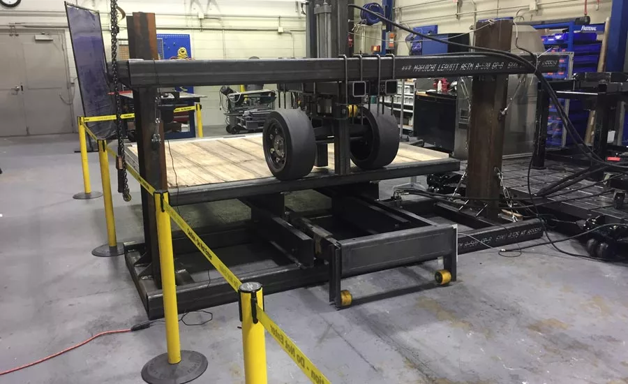
Figure 1. Box van floor test apparatus. The wheels are held in position, pressing downward on the floor segment while it is moved back and forth underneath.
The Knapheide Manufacturing Company of Quincy, IL, is a leader in the North American utility truck body market, so when they adopt manufacturing and testing procedures, the industry takes note. “In the old days we would send our products out to be tested to ensure that they met industry certification standards,” said Richard Pelnarsh, Knapheide test engineer, “but that used to be very expensive, and each test could take weeks to complete, impacting our ability to meet our schedules.” More recently, the company has been developing test systems in house, shortening the process and improving their ability to test customized product configurations. A custom test may also be developed when a need arises to recreate a particular set of events a Knapheide product will experience in the field.
The typical test involves applying a specific amount of force to an item such as a truck bed, bulkhead or a trailer hitch in order to simulate real-world usage conditions, cycling the application of force some number of times, and documenting the results. If a standard test protocol adopted by the SAE exists, then the Knapheide test group implements that. If not, then it is up to them to develop a test from scratch.
“Most of the safety tests performed are ensuring that a particular standard is met, for example there are floor load standards,” said Pelnarsh. “There is a floor loading test where we have to run a simulated forklift of 9,000 pounds moving across a truck floor 10,000 times.” The floor being tested (see figure 1) is made from wood, which would be found in a standard box van product made by Knapheide.
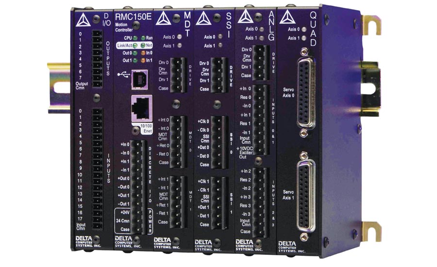
Figure 2. This is an 8-axis electrohydraulic motion controller.
The test stand uses a RMC151 eight-axis, dual-loop electrohydraulic motion controller manufactured by Delta Computer Systems Inc. of Battle Ground, WA (Figure 2). In selecting the Delta RMC, the Knapheide test team looked for a motion control solution that is capable of three things: 1) Flexibility in order to be reconfigured to test many different types of assemblies with different orientations and force ratings, 2) high precision in order to detect minute changes in the device under test’s response to the force, and to ensure repeatability from cycle to cycle, and 3) the ability to document the results. “A lot of the usefulness for the RMC is in doing one-off tests,” said Pelnarsh. “The Delta controller allows us to be very precise in our application of force and/or position.” Different test rigs developed by the Knapheide team are capable of applying up to 65,000 pounds to within plus or minus five pounds.
There are two motion axes being controlled in the box van test stand. The motion controller operates the hydraulics through a proportional servo valve feeding the cylinder that applies down force on the wheels. It also controls the hydraulic motor that moves the truck floor back and forth (instead of moving the simulated forklift, it was easier to move the floor). During the test, the down force is ramped up and down as the floor is moved. “What makes this application complex is that the motion of the floor and application of the force through the wheels needs to be precisely coordinated as they are cycled,” said Pelnarsh.
The motion controller connects directly to a rotary encoder on the hydraulic motor to keep track of the number of cycles, and a load cell on the hydraulic cylinder that tracks the pressure being exerted by the forklift wheels. Because the RMC 151 is a multi-axis controller it can synchronize, or time sequence the motion of up to eight motion axes simultaneously.
Delta motion controllers are supported by a software package called RMCTools. One of the tools in the package is the plot manager, which allows the test operators to view the motion parameter values in real time during a test. The plots (Figure 3 is a sample) also provide a documented record of each test cycle. In the plot, the blue line shows the position of the truck bed as it is moved back and forth. The yellow line shows the target force being applied downward on the wheels and the black line shows the actual force value as reported by the load cell. The goal in tuning a motion application is for the target and actual curves to overlap signifying that there is no error between the target and actual values. During the period of maximum force being applied, you’ll see that the black line looks jagged. This is caused by the wheels rolling across the structural members of the floor underneath the floor surface.
The green plot line in the figure shows the drive signal to the hydraulic valve operating the cylinder that provides downward force on the wheels. By precisely monitoring and documenting how the motion parameters over time, it is possible to discover how materials, such as the box truck floorboards, react to stress. In this manner, potential failure modes can be identified and studied without destroying the device under test.
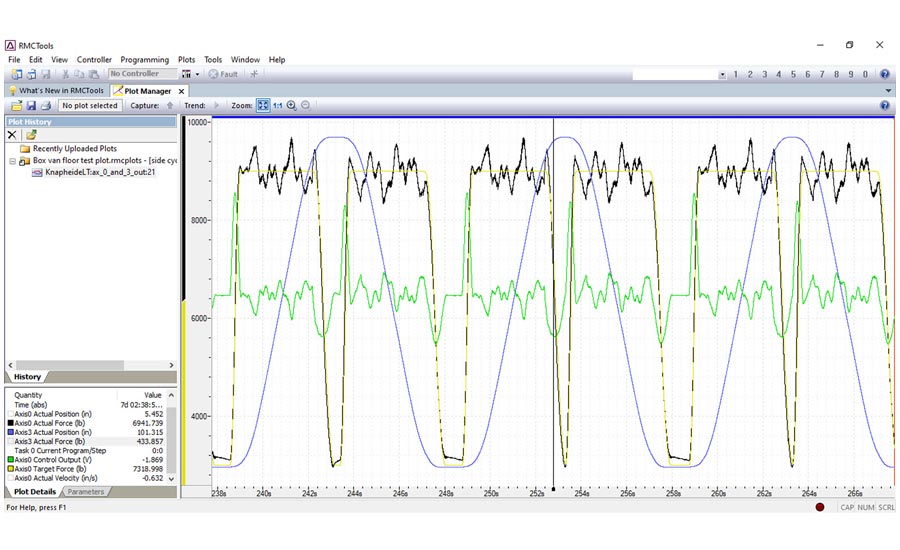
Figure 3. RMCTools plot of the truck bed test stand in operation.
To simplify the tuning of motion applications, Delta’s RMCTools environment contains a tool called the tuning wizard, which models the system performance to generate control loop gain recommendations to reduce the error between the target and actual motion profiles. “It only took us a week to completely set up, program, and tune this test stand,” said Pelnarsh. “We couldn’t have done it without the RMC.”
“Bottom line, with the test stand we built we can produce the same results in hours that would be seen in the field after years of use,” concludes Pelnarsh. All told, Knapheide has developed more than 200 tests so far using the same motion control hardware. The test lab is paying off for Knapheide in terms of the money saved that would otherwise have been spent contracting outside test labs.
Looking for a reprint of this article?
From high-res PDFs to custom plaques, order your copy today!


