A Quality Assurance Toolset for Modern Manufacturers
Before you can fully utilize machine vision, you need to understand the basics.
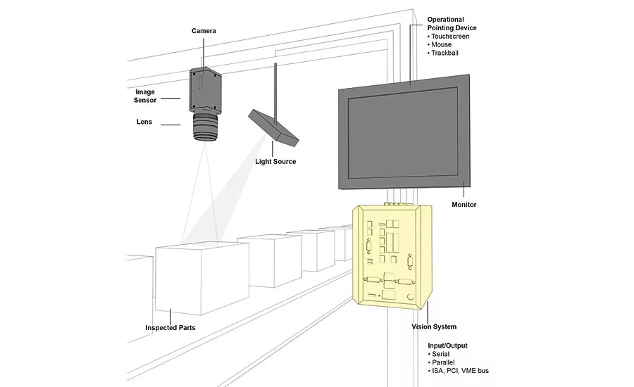
Figure 1: Main components of a machine vision system
The official definition of “machine vision” encompasses all industrial and nonindustrial applications in which a combination of hardware and software provide operational guidance to devices in the execution of their functions based on the capture and processing of images. In short, machine vision helps companies manufacture quality goods, repeatably. And since companies that manufacture defective goods don’t last long, the manufacturing world has turned to machine vision for the quality (re)assurance it needs. But before a company can fully utilize machine vision, it needs to understand the basics.
For example, modern machine vision systems rely on digital sensors inside industrial cameras with specialized optics to acquire images. After an image is acquired, computer hardware and software process, analyze, and measure various characteristics of the image for the purposes of automated decision-making.
Unlike manual inspectors, machine vision excels at quantitative measurements in structured scenes because of its speed, accuracy, and repeatability. For example, on a production line, a machine vision system can inspect hundreds, or even thousands, of parts per minute. At the same time, a machine vision system built around the right camera resolution and optics can easily inspect object details too small to be seen by the human eye.
Components of Machine Vision
The major components of a machine vision system include lighting, a lens, an image sensor, vision processing, and communications. Lighting illuminates the part to be inspected, allowing its features to stand out so they can be clearly seen by the camera. The lens captures the image and presents it to the sensor in the form of light. The sensor in a machine vision camera converts this light into a digital image, which is then sent to the processor for analysis.
The vision-processing step utilizes algorithms that review the image and extract required information, run the necessary inspection, and make a decision. Finally, communication is typically accomplished by either a discrete I/O signal or data sent over a serial connection to a device that is logging information or using it for some subsequent action.
Most machine vision hardware components, such as lighting modules, sensors, and processors, are available commercial off-the-shelf (COTS). Machine vision systems can be assembled from COTS components or purchased as fully integrated systems with all components in a single device, such as a smart camera solution.
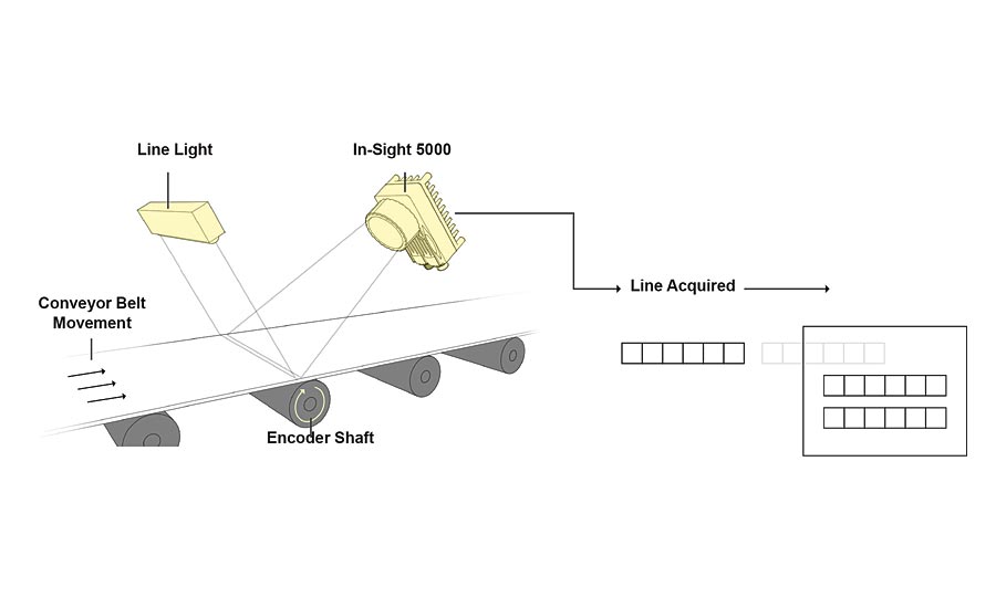
Figure 2: Line scan techniques build the 2D image one line at a time.
Lighting, Lensing, Sensors
Lighting is one key to successful machine vision results. Machine vision systems create images by analyzing reflected light from an object, not by analyzing the object itself. A lighting technique involves a light source and its placement with respect to the part and the camera. A particular lighting technique can enhance an image such that it negates some features and enhances others, by silhouetting a part that obscures surface details to allow measurement of its edges, for example. Common lighting configurations include bright field and dark field lighting, backlighting, diffuse light, structured light, and strobed or pulsed light.
The lens captures the image and delivers it to the image sensor in the camera. Lenses vary in optical quality and price, and the lens used determines the quality and resolution of the captured image. Most vision system cameras offer two main types of lenses: interchangeable lenses and fixed lenses. Interchangeable lenses are typically C-mounts or CS-mounts. A fixed lens as part of a stand-alone vision system can use fixed focal lengths or autofocus. If the system calls for greater depth of field than a fixed-focal-length lens can offer, designers can use either mechanically adjusted autofocus lenses or a liquid lens that can focus the optic based on an electric field.
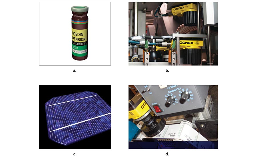
Figure 3: Line scan cameras can (a) unwrap cylindrical objects for inspection, (b) add vision to space-constrained environments, (c) meet high-resolution inspection requirements, and (d) inspect objects in continuous motion.
The camera’s ability to capture a correctly illuminated image of the inspected object depends not only on the light and lens but also on the image sensor within the camera. Essentially, the job of the image sensor is to capture light and convert it to a digital image, balancing noise, sensitivity, and dynamic range. Image sensors typically use complementary metal oxide semiconductor (CMOS) technology to convert light (photons) to electrical signals (electrons). In some scientific cameras, manufacturers use charge-coupled device (CCD) sensor technology, which is generally more expensive and less flexible.
The higher the resolution, the more detail an image will have and the more accurate measurements will be. Part size, inspection tolerances, and other parameters dictate the required resolution. A sensor’s resolution can be increased without significantly increasing the cost of the sensor by shrinking the size of each pixel. However, smaller pixels also make it tougher for the sensor and lens to work together to capture and convert all available light into a workable image.
Beyond resolution and pixel size, designers also need to choose among three general machine vision camera types, including 1D, 2D, and 3D sensors. Line-scan cameras, or 1D sensors, build an image one row at a time. Area array, or 2D imaging sensors, use standard sensor chips like those used in cellphones to take a picture of everything within the camera’s field of view in one acquisition. Finally, 3D imaging sensors use different techniques, including multiple cameras, to provide depth information in addition to height and width, similar to how a human sees their surroundings.
Each approach is effective at solving specific machine vision applications. For example, 1D imaging is useful for large surfaces, such as rolls of printed paper or large flat-screen glass panels. The most common machine vision application is the 2D inspection, where a camera makes a linear measurement or verifies a part or a feature, for example. Stereoscopic, structured light, time of flight (ToF), and other 3D imaging systems are often used for large parts where part height needs to be taken into account for inspection or motion control, as with vision-guided robot (VGR) applications where a robot manipulates objects in three-dimensional space.
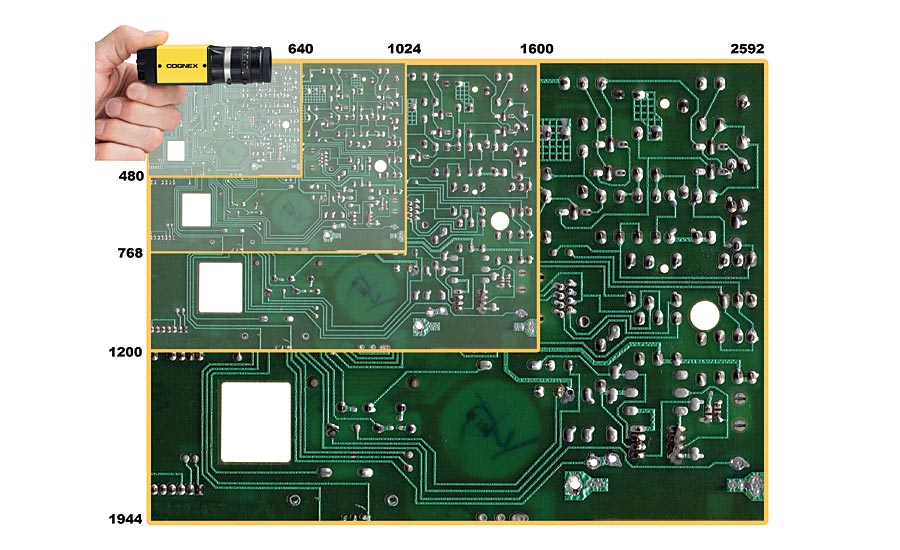
Figure 4: 2D vision systems can produce images with different resolutions.
Processing, Platforms, and Communication
Processing is the mechanism for extracting information from a digital image and may take place externally in a PC-based system or internally in a stand-alone vision system, such as a smart camera. Processing is performed by software and consists of several steps.
First, an image is acquired from the sensor. In some cases, preprocessing may be required to optimize the image and ensure that all the necessary features stand out. Next, the software locates the specific features, runs measurements, and compares these to the specification. Finally, a decision is made and the results are communicated.
While many physical components of a machine vision system (such as lighting) offer discrete specifications for the sake of comparison, vision system algorithms are a major differentiator among suppliers. Therefore, how well algorithms perform in specific installations should top the list of key components to evaluate when comparing solutions. Depending on the specific system or application, vision software configures camera parameters, makes the pass/fail decision, communicates with the factory floor, and supports HMI development—basically impacting every aspect of a machine vision system’s performance.
After the machine vision system has analyzed the images and made a determination, the system needs to quickly and easily communicate that data to other manufacturing equipment, networks, and computers. Typically this is done by either a discrete I/O signal or data sent over a serial connection to a device that is logging information or using it. Discrete I/O points may be connected to a programmable logic controller (PLC), which will use that information to control a work cell or an indicator such as a stack light, or directly to a solenoid, which might be used to trigger a reject mechanism.
Data communication by a serial connection can be in the form of a conventional RS-232 serial output or Ethernet. Some systems employ a higher-level industrial protocol such as Ethernet/IP, which may be connected to a device like a monitor or other operator interface to provide an operator interface specific to the application for convenient process monitoring and control.
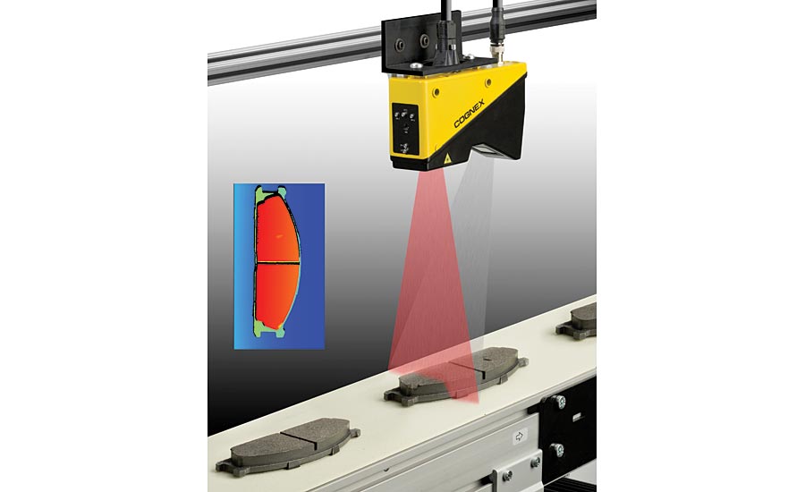
Figure 5: 3D inspection using a single camera
Machine vision implementation comes on several physical platforms, including PC-based systems, vision controllers designed for 3D and multi-camera 2D applications, and stand-alone vision systems, ranging from image-based bar code readers and simple vision sensors to powerful smart camera solutions. Choosing the right machine vision platform generally depends on the application’s requirements, including development environment, capability, architecture, and cost.
Machine vision is the automatic extraction of information from digital images for process or quality control. Most manufacturers use automated machine vision instead of human inspectors because it is better suited to repetitive inspection tasks. It is faster, is more objective, and works continuously. Machine vision can inspect hundreds or even thousands of parts per minute and provides more consistent and reliable inspection results 24 hours a day, 7 days a week.
Measurement, counting, location, and decoding are some of the most common applications for machine vision in manufacturing today. By reducing defects, increasing yield, facilitating compliance with regulations, and tracking parts with machine vision, manufacturers can save money and increase profitability. V&S
Which Machine Vision Platform is Best for You?
If machine vision algorithms are the blood of successful application, then the processing platform is the heart.
Machine vision designers have several options when it comes to physical processing platforms, including PC-based systems, vision controllers designed for 3D and multi-camera 2D applications, and stand-alone vision systems ranging from image-based bar code readers and simple vision sensors to powerful smart camera solutions. Choosing the right machine vision platform generally depends on the application’s requirements, including development environment, capability, architecture, and cost.
PC-based systems easily interface with direct-connect cameras or image acquisition boards and are well supported with configurable machine vision application software. In addition, PCs provide a wealth of custom code development options using familiar and well-supported languages such as Visual C/C++, Visual Basic, and Java, plus graphical programming environments. However, development tends to be long and complicated, so it is usually limited to large installations and appeals mostly to advanced machine vision users and programmers.
Vision controllers offer all the power and flexibility of a PC-based system but are better able to withstand the rigors of harsh factory environments. Vision controllers allow for easier configuration of 3D and multi-camera 2D applications, perhaps for one-off tasks where a reasonable amount of time and money are available for development. This allows more sophisticated applications to be configured in a very cost-effective way.
Stand-alone vision systems, such as smart cameras, are cost-effective and can be quickly and easily configured. These systems come complete with camera sensor, processor, and communications. Some also integrate lighting and autofocus optics. In many cases these systems are compact and affordable enough to be installed throughout the factory. By using stand-alone vision systems at key process points, defects can be caught earlier in the manufacturing process and equipment problems can be identified more quickly. These systems offer configurable environments that provide easy guided setup or more advanced programming and scripting. Some stand-alone vision systems provide both development environments, allowing for easy setup, with the added power and flexibility of programming and scripting for greater control of system configuration and handling of vision-application data.
Vision sensors and image-based bar code readers generally require no programming and provide user-friendly interfaces. Most are easily integrated with any machine to provide single-point inspections with dedicated processing, and they offer built-in Ethernet communications for factory-wide networkability.
Looking for a reprint of this article?
From high-res PDFs to custom plaques, order your copy today!


