Nondestructive Inspection of Automotive Computers
As with the testing and evaluation of raw materials, controlling the quality of electronic devices is essential
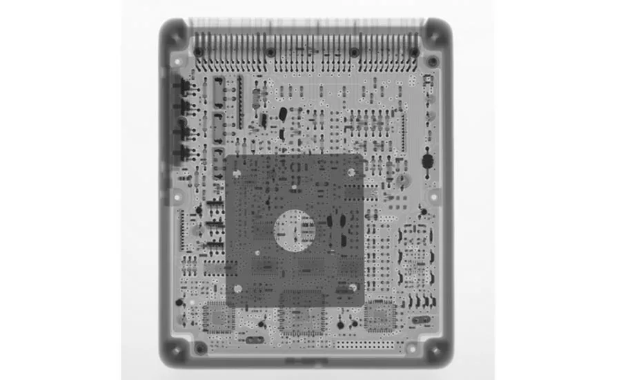
Figure 1: Two-dimensional X-ray image of entire electronic control unit (ECU)
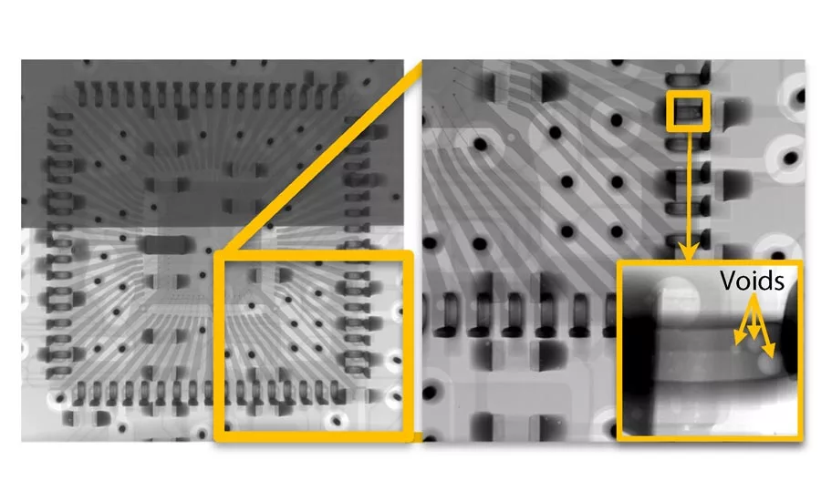
Figure 2: Two-dimensional X-ray images of IC package (left) and solder joint (right)
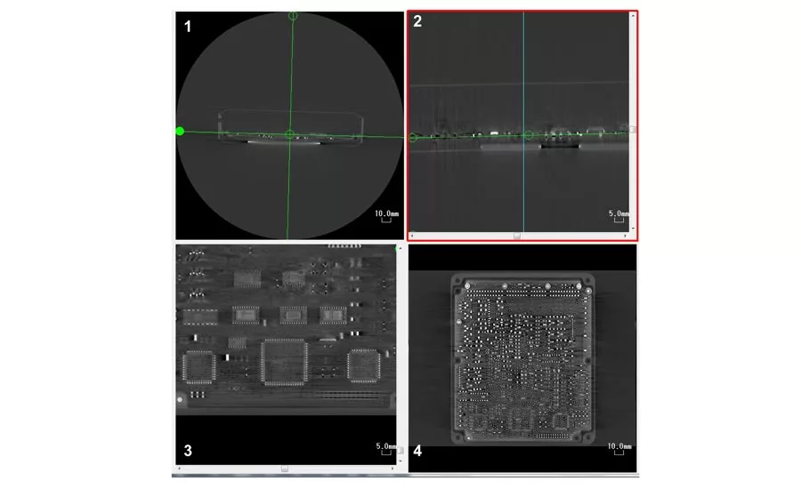
Figure 3: MPR images of ECU
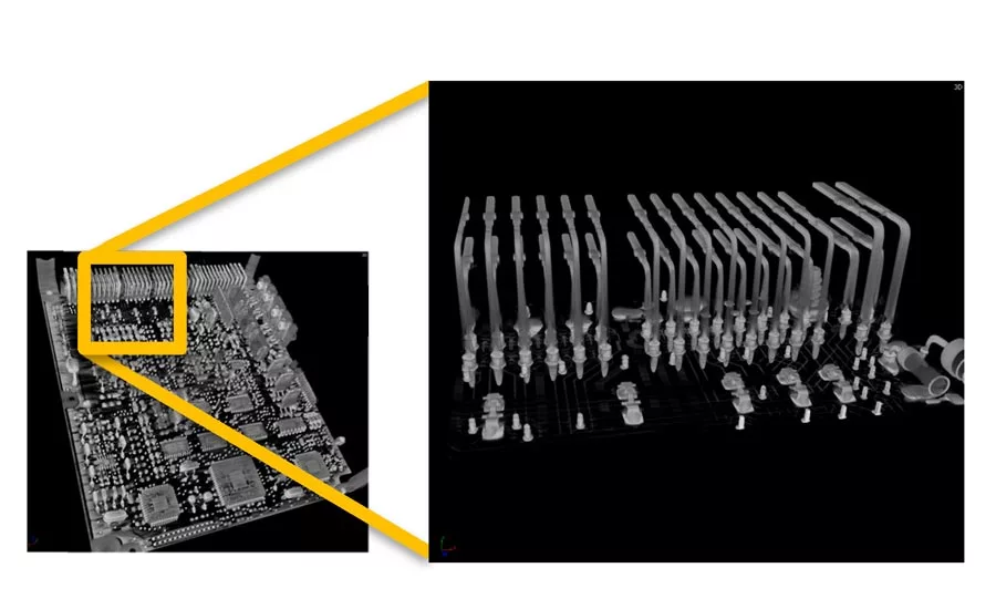
Figures 4: Volume rendering image for solder joints of a connector part
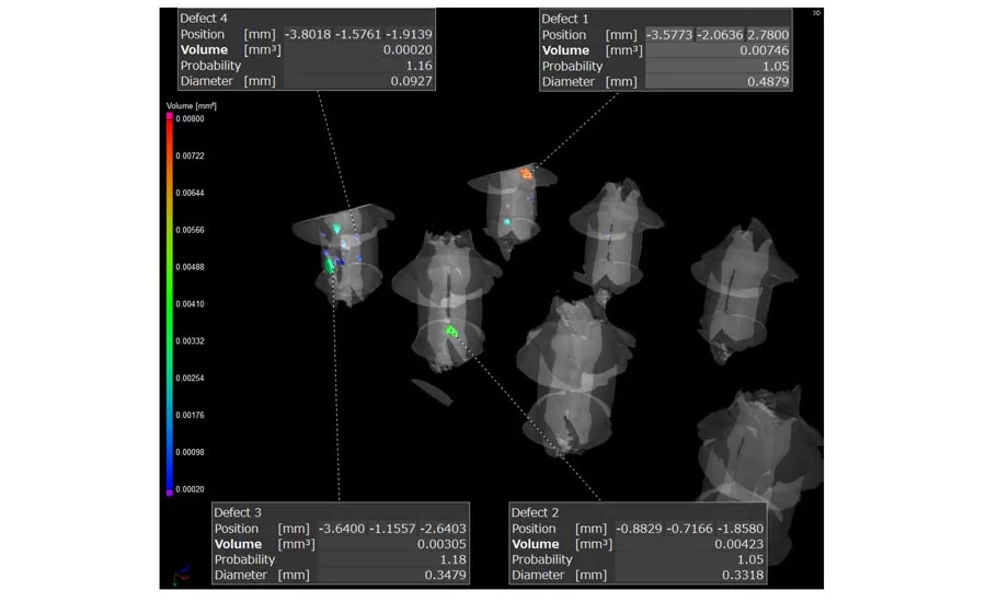
Figure 5: Analysis of voids in solder
In the automotive industry, quality control/assurance has often focused on the physical testing and evaluation of raw materials and finished products. From a safety perspective, it is imperative that the strength of these materials and products meets established standards. Tensile, compression, bending and hardness tests are used for these evaluations.
Thorough quality assurance requires evaluations of other characteristics beyond physical strength. The increasing complexity of safety-related functions, such as automated driving and erroneous start suppression functions, necessitates higher performance in the electronic devices which control those functions. In addition, the demands for improved fuel combustion efficiency and optimum control of the engine under varying running conditions has also increased. These control functions are performed by electronic control units (ECU), also called “car computers.”
ECUs contain many components which incorporate information from various sensors throughout the automobile in order to optimize engine combustion efficiency. They also contain components which both monitor and control the automobile, engine temperature, tire air pressure and other important conditions. The use of stacked boards and higher density components has also increased, allowing these devices to be installed in confined spaces.
Automobiles equipped with these electronic devices vibrate constantly while in operation and are affected by both ambient temperature changes as well as heat from the engine. As with the testing and evaluation of raw materials, controlling the quality of ECUs and other electronic devices is essential. That quality control requires a different inspection technique, as the devices are almost always enclosed in cases. Nondestructive X-ray testing meets this need by imaging the internal structures without disassembling the devices. In particular, microfocus X-ray computed tomography (CT) systems can identify three-dimensional locations of the small points of interest with depth information. These systems can find detailed imperfections with high-resolution imaging, providing more complete information and increased inspection accuracy.
Imaging Analyses of a Car Computer (ECU)
Figure 1 shows a two-dimensional X-ray image of an ECU scanned using a microfocus X-ray CT system. Two-dimensional inspection can find obvious imperfections, such as missing or damaged components and significant bends in the parts. The position of the board can also be identified, making it possible to check for physical contact between the board and the ECU case.
The internal structure analysis of electric components and more detailed solder joint inspection can be performed by increasing the magnification ratio. For example, figure 2 shows two-dimensional X-ray images of the area around an IC package (left) and a solder joint area scanned at a higher magnification (right). The internal wiring in the IC package and the solder joints are resolved on the left side, and voids in solder joints with the board can also be confirmed by further enlargement of the solder joint area on the right.
In addition to two-dimensional X-ray images, multi planar reconstruction (MPR) images can be obtained. MPR is a function that reformats a CT volume data set at arbitrary planes by virtually stacking Z-axial slices. As shown in figure 3, it is possible to display the CT image, as seen in (1), and cross-sectional images mutually orthogonal to (1), as in (2) and (3). This can also be done with cross-sectional images from any arbitrary angle, as in (4). In a CT image, lighter (whiter) areas represent structures, such as solder joints, electronic components, and the wiring of the board, having higher densities. Thus, one can confirm the presence or absence of parts and solder from this general image in three dimensions.
By utilizing specialized analysis and visualization software for industrial CT data, one can display a 2D projection of a 3D data set acquired using a CT scanner. This technique is called volume rendering. Using this technique, bent parts and the presence (or absence) of parts on the back side of the board can be intuitively visualized in 3D. This allows the operator to observe a shape closer to that of the actual object.
As an example, Figure 4 shows a magnified volume rendering image for solder joints of a connector. Although solder joints are used at many of the terminals, voids in the solder (if present) may coalesce and develop into cracks due to the repeated vibration and thermal expansion inherent to the operation of the automobile.
Figure 5 shows the characterized void distributions in solder joints. The voids are color coded by volume. Visualizing individual voids, identifying their locations, and calculating their respective volumes and surface areas enables objective, quantifiable measurement of quality control. By ascertaining the condition of defects from various types of quantified information and adjusting the reflow conditions accordingly, significant improvements in production yield and efficiency can be achieved.
Conclusion
X-ray computed tomography systems enable observation and analysis of assembled products without disassembly. By observing the internal state of components during different stages of quality control, these systems help to ensure consistent quality and reliability. The scope of work extends to more than just investigating potential product defects, though. They can be used in both production and development processes, helping to reduce costs and increase efficiencies.
Looking for a reprint of this article?
From high-res PDFs to custom plaques, order your copy today!


