Radiographic Image Interpretation: Doing it Right
The process of radiographic interpretation consists of many variables with the major objective being achieving the highest possible quality level.
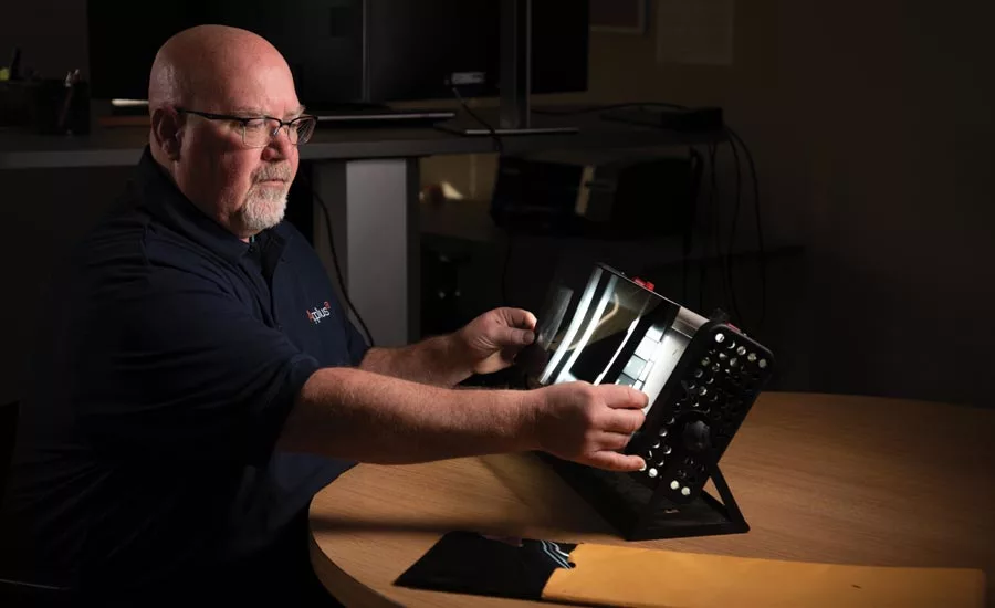
A qualified radiographer will maximize each variable in order to achieve the highest quality image even though the ideal technique may require additional time. Photo credit: Doug Miskell, ApplusRTD. Photo courtesy of Full Circle Studios LLC
Radiographs have been interpreted since Wilhelm Conrad Roentgen first observed the X-ray of his wife’s hand back in 1896. The process of radiographic interpretation consists of many variables with the major objective being achieving the highest possible quality level or sensitivity. Over the course of time since that first historic X-ray was taken, there have been many radiographs of many objects, interpreted by many individuals ranging from trainees to medical professionals. This article will focus on industrial applications with the sincere hope that it will improve the process in the future. The issue of interpretation has been the source of many disagreements, many times resulting in turmoil including unnecessary repairs and, in some cases, missed calls of conditions that should have been rejected. Improper disposition of serious discontinuities may result in product failure possibly causing costly downtime and injury to personnel. On the other hand, rejection of an acceptable discontinuity or condition can cause needless repairs resulting in significant cost and delays.
Objectives
The most significant objective to effective radiographic image interpretation is to achieve the highest radiographic sensitivity possible. This means being able to clearly observe the smallest change in the object being radiographed. This is only possible if the radiographers producing the image are qualified and understand the many variables and their impact on image quality. A qualified radiographer will maximize each variable in order to achieve the highest quality image even though the ideal technique may require additional time. They will also understand how both contrast and definition are related to achieving radiographic quality level. The quality ingredients include but are not limited to:
- Selection of the optimum energy level for the application. For radiographs taken with an X-ray source, it means selecting the optimum kV based on the part thickness.
- Using the film or imaging plate with the highest possible resolution. Film with finer grain which produces higher resolution will require longer exposure times, but the major benefit is greater probability of detection. The imaging plates have a greater dynamic range than film.
- Development of a technique that optimizes the variables; maximum practical source to object/detector distance, minimum object to detector distance, source to object positioning to provide alignment and minimize distortion, consistent film/imaging plate processing and handling procedure, to name a few.
- Film/image density, coverage, image identification.
The Interpreter
There have been discussions in the past regarding the qualifications of the interpreter. First, some terminology:
- Indication – the response, or evidence of a response, disclosed through a nondestructive test (in this case, radiographic testing), that requires further evaluation to determine its full significance.
- Interpretation – the determination of what is causing the indication. Indications in radiography may be false (such as image artifacts), nonrelevant (such as geometric or dimensional changes by design), and true or relevant (such as those resulting from discontinuities).
- Evaluation – a review following the interpretation of the indications in the radiograph to determine whether they are acceptable or unacceptable in accordance with the specified acceptance criteria.
- Detector – the radiographic film or imaging plate.
In order to be qualified to interpret/evaluate images, should a radiographic interpreter also be a radiographer? Not necessarily. It is essential that interpreters have a good understanding of the variables associated with the radiographic process and how they affect the quality of the image. This should also apply to oversight personnel such as auditors or the owner’s representative. To this end, SNT-TC-1A has recommended training hours for both Level I radiographers and non-radiographers. However, the employer’s written practice will stipulate the training requirements. There are also course outlines for RT image interpreters in ANSI/ASNT CP-105.
Key Elements for Effective Image Interpretation
- The Interpreter – is the major element in the interpretation and evaluation process. The personnel performing the interpretation must understand the variables involved in the RT process and understand how those variables affect the image. The visual acuity of the interpreter is of utmost importance. Annual vision examinations are required for all certified personnel. It would also be beneficial for the interpreter to pass a supplemental examination verifying their ability to distinguish the various shades of gray that are typically encountered in the radiographic image. A qualified interpreter should also hold an RT certification (Level II, Level II Limited, or Level III) and should have knowledge of:
- The RT technique used.
- The material type and thickness being radiographed.
- The film classification and imaging plate type.
- Possible discontinuity types to be encountered.
- The quality level required.
- The applicable codes/standards and acceptance criteria.
- The reporting requirements.
- Training – The typical training courses in RT Levels I and II do not address the subject of image interpretation adequately. A forty-hour course is hardly enough time to do it properly when the curriculum has to cover so many subjects. The fact that there are so many variables involved with the interpretation and evaluation of radiographic images should support the need for extended training. Many courses use such standard radiographic images as the ASTM casting reference standards, IIW weld defect reference collection, and those provided through the instructors’ private collection. Ideally, the radiographs used in the courses should include real world images as well as those to be encountered by the interpreter. Perhaps someday an enterprising organization will compile an extensive set of ideal radiographic images that cover the spectrum of applications and make them available to NDT companies and training schools.
- The Equipment - Verification that the image viewer and densitometer are working properly before performing the interpretation is essential. The high intensity film viewer to be used for film interpretation and evaluation should be checked for brightness and to assure that the variable intensity control and all the bulbs are working properly. It is also important that the viewing window of the viewer provides a diffuse light. It should also be clean and free of artifacts or other blemishes that could cause distractions during the interpretation. The density strip should be checked to assure it meets the current requirements for traceability to a national standard. The room or area where the images will be interpreted should provide subdued lighting to minimize the glare on the image surface.
- Prerequisites – It’s good practice to take an initial look at the image to observe the overall quality based on the contrast and definition. The first step is to confirm that the quality level has been achieved by observing the Image Quality Indicator (IQI). The second step is to confirm that the density is acceptable using the densitometer for film or the density scale for digital images. It is important to assure that the entire area of interest meets the density requirements. Third, coverage of the area of interest should be confirmed.
- Useful Aids - The use of magnifying devices is usually optional and should be used with a degree of caution. Very high magnification can cause difficulties in the resolution of discontinuities due to the enlargement of the grains in the film or in the digital image. Other suggestions include the use of cotton gloves to prevent fingerprints on the image and a small flashlight should be available to assist in the identification of image scratches and other artifacts on the film surface. Once accomplished and all prerequisites are addressed, the review can commence.
-
The Review – There’s much more to interpretation than just looking at the image for indications of density change. The interpreter must be able to recognize any false indications (artifacts) that may be cause for rejection if they occur within the area of interest. Such indications can be caused by dirt or other foreign objects between the film and intensifying screen, scratches in the intensifying screen, fingerprints, film scratches, crimp marks, static electricity marks, pressure marks, light leaks, Pi lines from automatic processors, etc. Indications that may be from the part surface should be so noted on the report and confirmed by verification.
After verification that the image quality level is acceptable and the density requirements are met, the actual review can begin. Key factors when interpreting the indications of actual discontinuities include their shape, density, location, orientation and size. - The Report – All the essential elements must be addressed on the radiographic report including:
- Company name performing the RT.
- Name and contact information of the customer.
- Date and reference number of the report.
- Applicable codes/specifications.
- Part description – identification, material type, dimensions, welding/casting process.
- Procedure, technique details, film/imaging plate used, shooting sketch, IQI used, quality level required.
- Interpretation data – location, density readings, quality level achieved, discontinuities observed, artifacts noted, surface conditions verified, accept/reject, name, signature and certification level of radiographers/interpreters, and if applicable, client signature/acceptance.
-
Interpretation Disputes – Since radiographic testing is a combination of technology and art, there will be times when interpreters do not agree. Disagreements may be between the NDT company and the customer, the owners and regulators, or between Level III’s. Some of the primary reasons for these disputes include quality levels (is the 2T hole image clearly discernable?), discontinuity types (is it a crack, lack of fusion, incomplete penetration?), density readings, coverage, etc.
How are disputes resolved? Most commonly with an independent third-party specialist. Also, many disputed images can be resolved by having another radiograph taken of the disputed area—preferably with an improved technique to provide an improved image. - Oversights – Lead letter “B” on the back of the film holder is not always used, procedures not readily available or followed, radiation monitors not used (film badges, dosimeters, survey meters, alarms, etc.), image identification (missing station numbers), improper IQI used, density readings of area of interest missing/not recorded, the qualification/certification of personnel.
Acknowledgements
The author wishes to thank Michael Shakinovsky, independent consultant who reviewed and provided excellent input for this article.
Looking for a reprint of this article?
From high-res PDFs to custom plaques, order your copy today!


