A New Angle on Aerospace FSW Inspections
The most effective inspection method for friction stir weld flaws is phased array ultrasound.
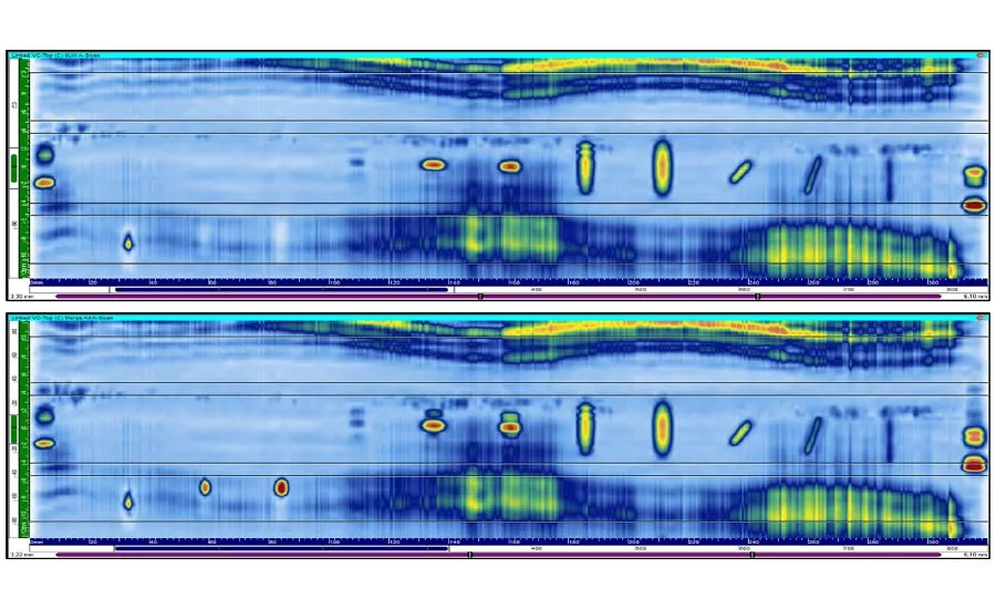
Figure 1: On a test piece with artificial flaws, the top image shows a 0°LW scan only of the weld center line. The bottom image shows a merged view of all data groups—0°LW and ±45°SW—and demonstrates more accurate length sizing and reduced noise level.
Friction stir weld (FSW) inspections in aerospace manufacturing are challenging for ultrasound technicians not necessarily because they require specialized computations or complex techniques but because scanning with conventional probe setups can be so time consuming.
FSW is used for aluminum lap-joint and butt welds on many of the industry’s biggest aluminum alloy structures, from rocket boosters and fuel tanks on launch vehicles to fuselage panels and wings on airplanes. The process uses a machine to firmly clamp two workpieces together and press a rotating spindle into the joint line. It moves quickly along the seam, creating friction and heat that cause the adjacent metals to become plastic. They flow from the front of the tool to the trailing edge where the grains mix together and recrystallize to produce a strong, highly efficient bond.
Properly calibrated, an FSW machine can quickly produce long runs of welds that use no filler and produce little waste, a big advantage for weight-conscious aerospace manufacturers.
Flaw Types
A friction stir weld has three distinct zones: an outer heat affected zone (HAZ) where the metal’s properties are affected but no deformation occurs; an inner thermo-mechanically affected zone (TMAZ) where grains are deformed but not mixed; and a stir zone or “nugget” comprised of very fine equiaxed grains.
Because the joining process involves relatively low peak temperatures and the materials are in a solid state throughout, friction stir welds aren’t susceptible to the type of porosity, cracking, distortion, and other discontinuities that can occur after metals are melted and then solidify.
Indeed, most FSW flaws are related to setup issues with the machine and materials. Improper spindle rotation speeds, rates of travel, lack of penetration or forging pressure, and gaps along the seam from a poor fit-up or clamping action can generate excessive or insufficient heat and an improper bond.
FSW flaws fall into two categories: volumetric voids like “wormholes” and cavities, and joint-line flaws like “kissing bonds,” where two butted materials fail to coalesce completely, and “hooking,” an uplift of surface oxides on the advancing side or retreating side of a lap weld.
A probe optimized for FSW is capable of generating ±45°SW scans inside the material as well as 0°LW with a single probe orientation.
Typical Procedures
The most effective inspection method for FSW flaws is phased array ultrasound done shortly after the weld is complete while the component is readily accessible.
In most cases, phased array UT is more practical to deploy compared to penetrant testing or radiography, which require more time to prepare for an inspection.
A portable phased array UT instrument with dual (2D) matrix array probe assemblies give NDT technicians the ability to build efficient scan plans, conduct lateral scans and create three-dimensional representations of the weld, and detect mis-oriented and transverse flaws.
However, covering the entirety of the weld with phased array UT requires multiple beam angles. Technicians have several different options to accomplish this.
For a butt-joint weld, the recommended technique for transverse flaws involves linear electronic scanning with two different refracted angle orientations: a +45° shear wave and a symmetrical -45° shear wave (+20° and -20° incident wave angles in immersion).
In the case of a lap-joint weld, the same two beam angles (+45°SW and -45°SW) are used in conjunction with a 0° longitudinal wave, which is the ideal angle for detecting joint-line flaws.
Performing the inspection with a standard single 64-element probe requires multiple setups and scanning sequences. A lap-joint inspection would involve separate sequences at +45°SW, 0°LW, -45°SW, with the technician stopping in between scans to realign and recalibrate the probe. A butt joint would require two separate scans at +45°SW and -45°SW.
Interrupting the test to manipulate the probe orientation every time another refracted angle is required is tedious but necessary due to the limited steering capability of a probe that’s not designed for FSW inspections.
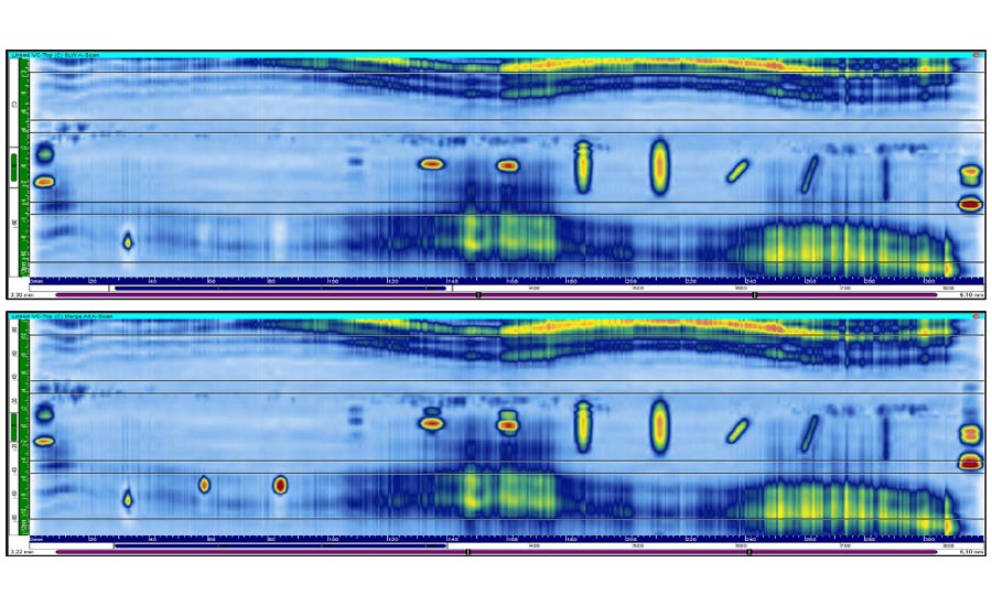
Figure 1: On a test piece with artificial flaws, the top image shows a 0°LW scan only of the weld center line. The bottom image shows a merged view of all data groups—0°LW and ±45°SW—and demonstrates more accurate length sizing and reduced noise level.
Optimized Solutions
A time-saving alternative is to have multiple probes and multiple phased array UT instruments set up and ready to go for each sequence. This approach certainly can work but it adds cost to the inspection process.
Another option is to use a 1D linear array probe with 128 elements that can simultaneously generate 0°LW and 45°SW beams for flaws parallel to the weld center line without probe inclination, and 45°SW for detection of transverse flaws when inclined in the secondary plane. Such a probe can obtain full volumetric coverage of the weld zone in a single scanning sequence and allow better detection of skewed flaws and accurate sizing compared to other solutions.
In an effort to demonstrate the efficiency of such a probe, UT engineers generated a side-by-side comparison of scan results obtained by using a 10 MHz, 64-element probe and the optimized probe on an aluminum test plate with notches.
At a frequency of 7.5 MHz, the optimized solution demonstrates more accurate length sizing and a reduced noise level, an improved lateral beam spread, and a greater tolerance to the rough surface conditions of a stir weld. Another consideration is the reduced presence of undesirable artifacts in the signal.
The same specimen was also subjected to a 0°LW scan. In figure 1, the bottom image shows a merged view of all data groups—0°LW and +/-45°SW—and demonstrates more accurate length sizing and reduced noise level.
Because all required refracted angles are generated with a single probe positioned at a normal incidence with respect to the inspected specimen surface, this alone simplifies the probe installation and alignment method since all that’s now required is to install it in the 0° scanner head.
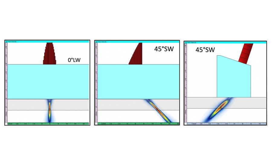
Figure 2: A dedicated FSW inspection technique with inclined probe provides excellent detection capability on transverse flaws.
Once the probe orientation is set, the 10 MHz, 64-element probe with one single UT channel configuration has an acquisition rate of approximatively 60 Hz, meaning an inspection speed of 60 mm per second with a 1 mm displacement increment per second.
For a complete setup, including three channels at +/-45°SW and 0°LW at maximum linear resolution, the optimized system can reach a speed of 30 mm per second. However, the optimized solution has three channels instead of one, which is the equivalent to three passes with the other probe. The linear resolution is greater, meaning more data is acquired. If the resolution is modified to match the 0.5 mm of the 64-element probe, it’s the equivalent to doubling the probe’s speed. Moreover, the optimized system streamlines the inspection time compared to the standard probe because the setup is simpler.
If even faster inspection speeds are required, two optimized probes can be used on two units in parallel to reach up to 50 mm per second at maximum resolution, or three pairs can be used for up to 100 mm per second. As with any multi-instrument or multi-probe solution, the tradeoff is additional cost and complexity.
Aerospace is an industry where productivity and cost control are a constant focus, especially given the pressures on manufacturers today. Total inspection time is critical to an efficient assembly process overall. A reliable phased array UT inspection solution for friction stir welds should incorporate rapid setup, quick calibration, and faster inspection speeds. Q
Looking for a reprint of this article?
From high-res PDFs to custom plaques, order your copy today!


