Aerospace | Back 2 Basics
How Eddy Current Array Takes Aerospace Inspection to New Heights
One of the great advantages of this technology is its capability to adapt to various materials and geometries.
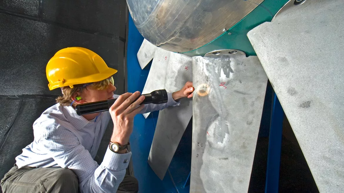
Source: Getty images
The continuous ground-breaking advances in the aerospace industry put more and more pressure on nondestructive testing (NDT) equipment manufacturers to be proactively solving new inspection challenges. Whether those challenges are brought by the use of new materials, new manufacturing techniques, or simply by an increasing volume of parts to inspect, they demand that NDT technologies remain highly flexible and open to innovation. As such, the recent advances in eddy current array (ECA) have considerably expanded the range of components and assets that can be inspected for surface and near-surface flaws.
THE BASICS OF EDDY CURRENT ARRAY
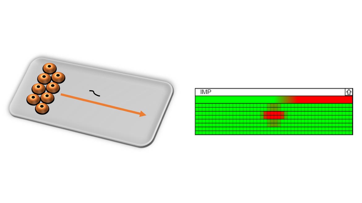
ECA consists of a probe or sensor that contains multiple coils placed in close contact with the conductive surface being inspected. The coils will induce eddy currents (localized electrical currents) in the material and will then measure changes in the magnetic field caused by the presence of flaws such as cracks, pits, or porosities. As the probe moves along a component, it creates a C-scan, which is a 2D representation of the inspected surface that usually highlights indications of flaws with high-contrast colors. Multiplexing is commonly used to avoid signal interference between nearby coils.
One of the great advantages of this technology is its capability to adapt to various materials and geometries. By transmitting and receiving signals with one another, ECA sensors enable detection performance that cannot be reached with traditional single-element probes. ECA is also significantly faster, less operator dependent, and easier to automate. Designing an industrial ECA system involves controlling dozens of interrelated parameters. Out of those, the following four are at the core of any ECA probe development:
Aerospace
A Quality Special Section
- Coil Size: Using smaller coils increases the resolution of an ECA probe and allows the detection of smaller flaws. However, smaller coils will be more sensitive to lift-off noise. They will also have a more limited depth of penetration of the eddy currents into the material: as a rule of thumb, an eddy current coil can penetrate a depth equal to approximately its size.
- Frequency: The electrical frequency also has a direct effect on the depth of penetration. A lower frequency allows the currents to penetrate deeper and enable subsurface flaw detection. On the other hand, increasing the frequency concentrates most of the electromagnetic energy on the near side of a material and is ideal for detecting surface-breaking flaws.
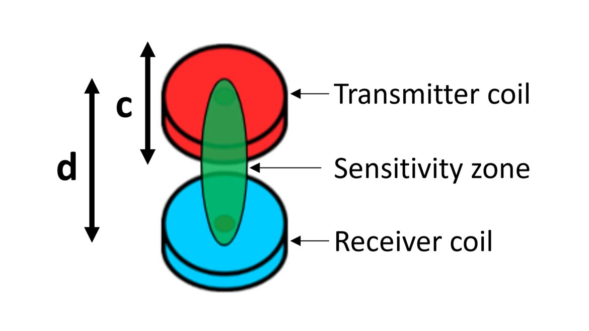
- Eddy Current Topology: In ECA, a topology is defined as the geometrical arrangement of the transmitter and receiver coils forming the eddy current channels. One coil induces eddy currents into the material under inspection, and a second coil measures the resulting magnetic field in order to detect potential flaws. A straight line connecting the transmitter and receiver coils represents the orientation of flaws that can be detected, and the extent of the sensitivity zone. The distance d between a transmitter and a receiver each of size c will have a major impact on the quality of the results. A topology with d ≈ c is referred to as “short transmit-receive” and is ideal for the detection of small surface-breaking flaws. A topology with d ≈ 2c is referred to as “long transmit-receive” and offers additional penetration for the detection of subsurface flaws.
- Probe Mechanics: Parameters like surface geometry, magnetic properties, roughness, restricted access around the part to inspect, mechanical stability, and the need for data encoding all need to be carefully considered when developing an ECA system, in order to make the inspection as easy and operator independent as possible.
AEROSPACE APPLICATIONS
All this knowledge is put to good use when developing new ECA probes for the early detection of integrity threats in aviation and aerospace applications.
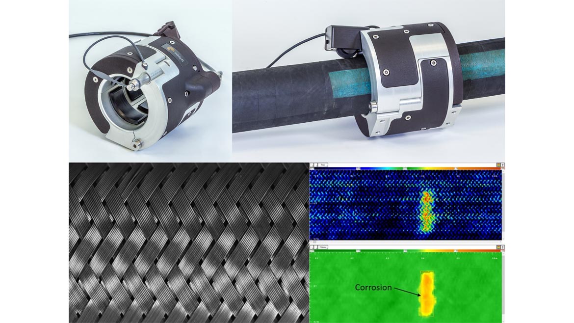
As a first example, flexible hoses used for air-to-air refueling of fighter aircraft and helicopters tend to get infiltrated with water, especially in high-humidity climates. This often leads to the rapid and unpredictable degradation of the underlying braided steel structure of the hoses, due to corrosion. By using a custom-built bracelet probe with large coils driven at high frequency, it is possible to concentrate eddy currents into the potentially corroded steel and average the signal over a large area, allowing discrimination of the signal of corrosion from that of the braid.
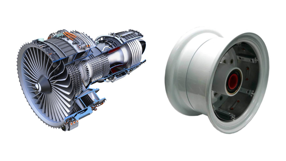
ECA probes can also be customized for the inspection of irregular surfaces and tight gaps of all sorts. Jet engines and aircraft wheels are two examples that are mostly made of irregular bends and radii that can be challenging to inspect with conventional NDT methods. Whether it’s for detecting cracks in the different stages of a turbine spool, at the surface of titanium turbine blades, in cooling holes, in fuel lines or simply at the root of a wheel radius, the strategy is usually the same: a rigid or semi-flexible probe is built to conform to the exact geometry to inspect. It uses the smallest coil size possible, driven at high frequency and using a short topology in order to maximize the sensitivity to submillimeter surface imperfections.
One last application that has been increasing interest for ECA over the past few years is the inspection of orbital welds in feed lines and hydraulic lines of spacecraft. The integrity of these welds is critical: they ensure that the lines are leak-free and able to withstand the extreme temperatures and pressures of spaceflight. While these welds are typically inspected with dye penetrant testing and radiography, the process can take over one hour per weld and is difficult to automate, even for newly produced welds. ECA probes have recently been developed with very small coils operating in a long topology, allowing penetration of the weld and detection of external and internal cracks, as well as clusters of porosities in the weld, all in a single scan. With a scan cycle that can be completed in less than a minute, is easy to automate, and removes all operator dependency, ECA positions itself as a strong contender to become the most used and most efficient technique for the inspection of orbital welds.
In conclusion, the aerospace industry’s continuous advancements require NDT equipment manufacturers to match the pace and be proactive in solving new inspection challenges. The use of eddy current array in aerospace inspection takes the industry to new heights by providing more a comprehensive and efficient inspection method that enables the industry to keep up with demands of the future.
Looking for a reprint of this article?
From high-res PDFs to custom plaques, order your copy today!


