Test & Inspection
Eddy Current Inspection of In-Service Aircraft Structure
Eddy current inspections are particularly sensitive to crack, corrosion, and other conductivity changes within electrically conductive alloys.

In production, every aircraft structure component will undergo inspection by one of the primary NDT methods. In-service aircraft will experience subsequent nondestructive testing, eddy current inspection being one the primary methods. This article serves to highlight the more common forms of eddy current applications on in-service aircraft.
With a few exceptions, general aviation aircraft are not pressurized at altitude. However, when business and commercial aircraft climb to altitude, e.g., 15,000 to 40,000 feet, the cabin is pressurized for passenger comfort. Since the pressure inside the cabin is greater than the outside, the fuselage will elongate and expand in diameter. When the aircraft lands and completes this flight cycle, the plane returns to its normal shape. This repetitive expansion and contraction eventually lead to metal fatigue and the possible initiation of cracks, whether it be fatigue cracking, stress corrosion cracking, or a stress rupture crack.
Regardless of which of the following specific inspections are performed, a test reference standard is utilized to standardize the inspection. The conductivity reference standard will represent a range of conductivities with the test subject nominal conductivity included. All the other test standard replicates the approximate conductivity and structure of the expected test subject. A calibration feature will be included in the reference standard, whether it be a machined groove, sawcut, or EDM notch. The dimensions of the calibration feature will dictate the size of the detected discontinuity. These reference standards will be referenced in the maintenance manual or service bulletin.
Conductivity Inspection
Eddy current inspections are particularly sensitive to crack, corrosion, and other conductivity changes within electrically conductive alloys such as aluminum, titanium, and steel. Changes in conductivity are one of the simplest forms of this inspection method. If, for example, a single engine turboprop plane suffered a tire catching on fire during landing, perhaps a lower wing spar will suffer subsequent heat damage. This damage manifests itself as a change in electrical conductivity. A wing spar with a production conductivity of 28% International Annealed Copper Standard (IACS) may show a conductivity of 34% IACS after a fire, indicating a loss of heat treatment that would prompt a removal and replacement of the spar. Modern impedance plane eddy current units are very portable (Figure 1). With the correct probe attached, many have the software capabilities to display a numerical value of the IACS conductivity on the screen.
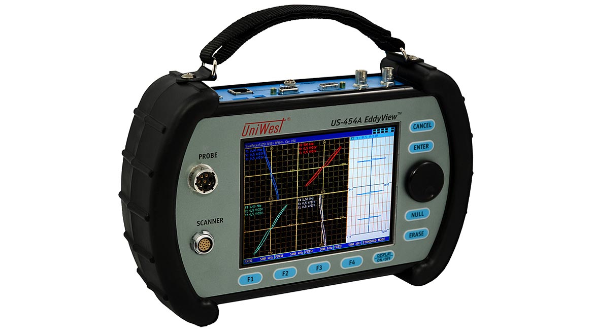
Figure 1. Portable Eddy Current Impedance Plane Unit. Source: Uniwest (Click on the image to enlarge.)
Surface Crack Inspection
Many maintenance manuals and service bulletins will mandate a simple surface scan using a pencil probe that operates within a frequency range of 100 to 500 kHz (Figure 2). These probes are available in varying configurations to facilitate specific test scenarios. They are often “shielded” with an alloy such as copper, brass, or aluminum to constrict the eddy current field to only the circumference of the test coil (0.070” diameter) for a compounded diameter of 0.120”. This small probe contact area can make manually inspecting for a small crack over a large surface area both time-consuming and tedious. However, high frequency inspection is tailor made to detect very small cracks very close to bolt holes and other edges where crack initiation is likely. Since cracks originate at the surface of the component, the test is designed to produce high eddy current density close to the surface. Depending upon the test frequency used and the conductivity of the aluminum alloy, this inspection concentrates the eddy current inspection to approximately the top 0.020” of the test subject.
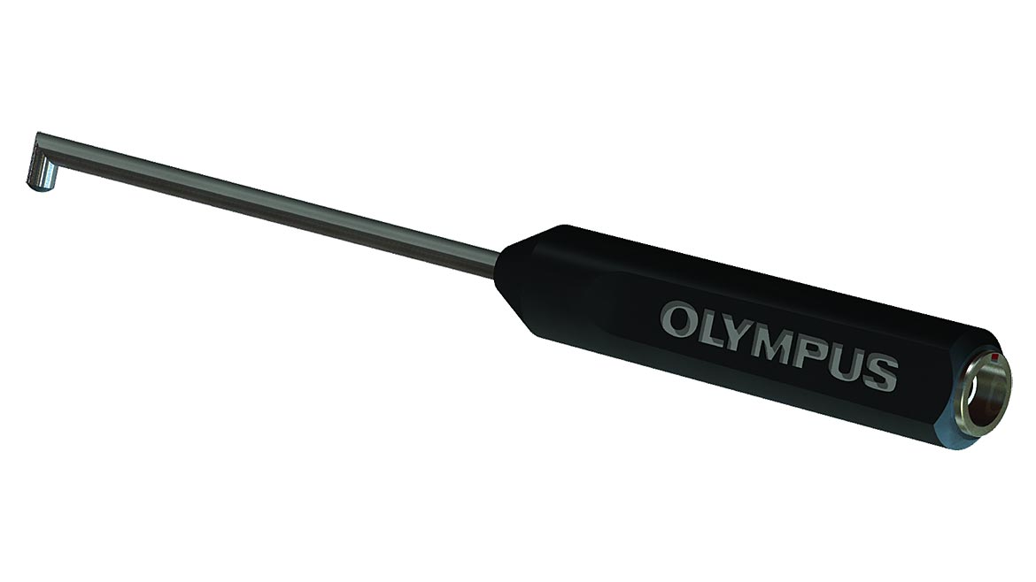
Figure 2. Pencil Surface Probe. Source: Olympus (Click on the image to enlarge.)
Bolt Hole Rotary Scanner Inspection
Eddy current inspectors still use manual bolt hole surface probes to inspect bolt holes, but rotary scanners (such as the one pictured in Figure 3) have been available for more than thirty years. They facilitate an inspection that is less operator dependent, being more consistent with their coverage as well as offering considerable time savings. Instead of the normal single coil (absolute) configuration used in a surface scan, the scanner uses a probe with a “differential,” two coils side-by-side, arrangement. This coil arrangement overcomes the test coil spacing variability encountered with oblong holes and can detect cracking closer to edges and interfaces of a multi-layer hole, e.g., skin and chord combination. Modern instruments offer multiple types of displays that are helpful to signal interpretation such as the combination of time-based sweep display and an impedance plane (Figure 3), or even a C-scan display similar to that used in ultrasonic inspections.
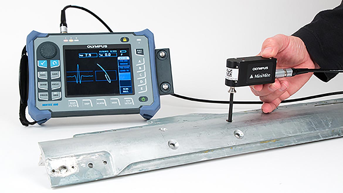
Figure 3. Bolt Hole Inspection Using a Rotary Scanning Probe. Source: Olympus (Click on the image to enlarge.)
Sliding Probe Doubler Or Skin Lap Inspection
The sliding probe (Figure 4) is particularly useful for inspecting holes in painted structure where a titanium fastener location may not be readily visible. By identifying two fastener locations some distance apart in a row of fasteners, a probe guide can be positioned to permit the sliding probe inspection of several fasteners in a row. The inspection can be performed even when the fastener location is hidden under paint. A sliding probe can inspect a row of holes with installed fasteners for a surface or subsurface crack, including the counter-sink portion of the bolt hole, three or more times faster than an inspection using an eddy current spot probe. Moreover, when inspecting multiple layers of aluminum with a nonconducting layer of adhesive bond between skins, this probe’s electromagnetic field penetrates to the subsurface member to generate eddy currents. There are multiple configurations of the sliding probe, but one configuration features two coils, one being the driver coil and other is the pickup or sensing coil. Test frequencies range for 1 kHz to 50 kHz, putting this in the category of a low frequency eddy current test.
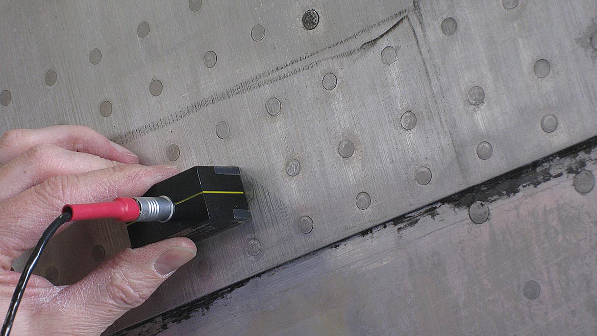
Figure 4. Sliding Probe Doubler or Skin Lap Inspection. Source: Olympus (Click on the image to enlarge.)
Subsurface Corrosion Inspection
In general, an airplane body skin or wing panel can have a thickness reduction up to 10% from its nominal thickness and still meet design strength requirements. Corrosion on the back side of an airplane skin can reduce the skin thickness, weakening the structure as well as creating stress risers that could initiate cracking. The proper spot type probe (Figure 5) driven at the proper test frequency can be very effective for detection of subsurface corrosion that might prompt structural repair such as a doubler installed over the thinned area or replacing the skin altogether.
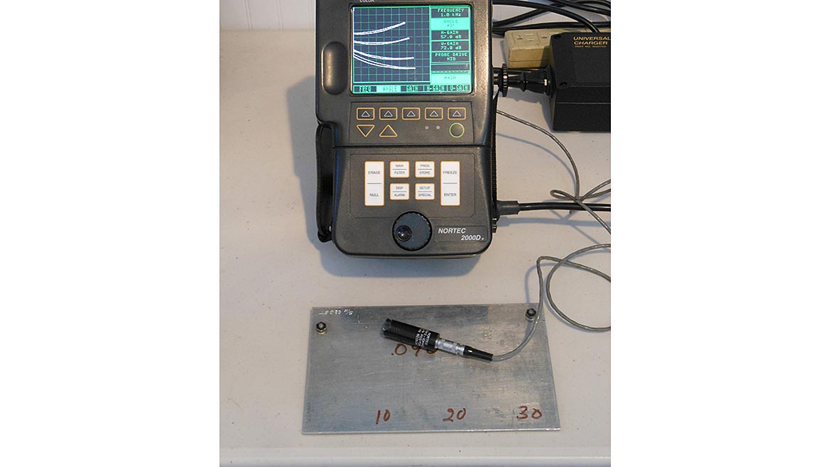
Figure 5. Corrosion Inspection Test Setup. Source: Level III Resources (Click on the image to enlarge.)
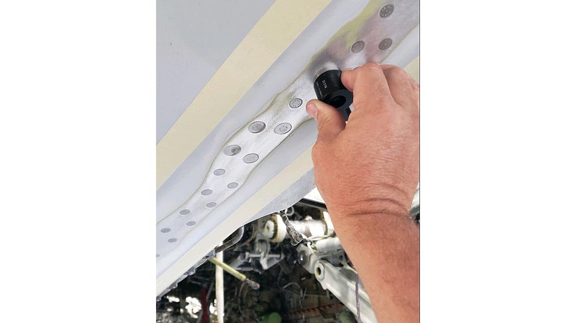
Figure 6. Low Frequency Second Layer Inspection. Source: Morrow NDT Services (Click on the image to enlarge.)
Reflection Probe Second Layer Inspection
Two common probe configurations for sub-surface or second layer inspection are spot probes and ring probes. Both are what is termed a reflection probe and operate at lower test frequencies for deeper penetration. Reflection probes use separate coils for inducing an eddy current in a conductor and detecting the magnetic field produced by the induced eddy current. The spot probe is not placed over the fastener, but are indexed around, between, or past fasteners that are installed flush with the aircraft skin. The ring probe is placed over the top of a fastener (Figure 6) to perform a 360-degree inspection around the fastener hole searching for a subsurface crack. One might suspect that the titanium fastener present during the inspection will affect the test results. However, the eddy current signal from a hole with a low-conductivity fastener, less than 3.0% IACS, is approximately the same as that of an open hole. As an example of the capabilities of this inspection, the skin and the underlying chord on a Boeing 747 are each 0.500” thick. Using an impedance plane multi-frequency unit, the inspector can inspect for subsurface cracks in the skin at 400 Hz and the chord at 100 Hz simultaneously, in effect reducing the inspection time in half.
Conclusion
Less common in-service applications include nonconductive coating thickness inspection and the up-and-coming applications for array type probes. Array probes have multiple individual coils arranged in a single probe such that complete coverage of a wide area on the aircraft are accomplished with a single scan and the results displayed as a computerized C-scan output (see July 2016 issue of Quality). In-service airframes offer many challenging inspections for the NDT professional. Yet, confirming the integrity of a vessel that so many lives depend upon is a rewarding endeavor for any inspector.
Looking for a reprint of this article?
From high-res PDFs to custom plaques, order your copy today!


