NDT | Back 2 Basics
The Basics of Digital X-Ray Inspection
Conventional Radiography Will Continue to Have a Pace in NDT, but Digital Radiography is the Future
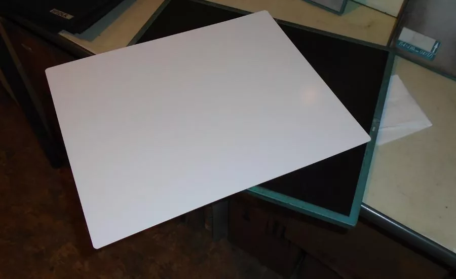
Figure 1 - CR Phosphor Plate Outside of a Rigid Cassette. Source: Alloyweld Inspection
Digital Radiography History
Both CR and DDA were originally developed exclusively for medical radiology. Medical CR was initiated in the early 1980s while DDA use began in the late 1990s. These modalities have basically eliminated the utilization of film in the modern medical, dental and veterinary industries. During the 1990s, CR was the first method to be utilized for industrial nondestructive testing (NDT). ASTM has facilitated the growth of these digital techniques with the establishment of various standards that offer standard practices and guides that provide standardization within both the industrial and aerospace industries. The primary NDT qualification and certification documents, SNT-TC-1A and NAS 410, were revised in 2011 and 2014 respectively to detail additional training and experience that would enable personnel certification in digital radiography.
In the digital age we live in, a common misconception associated with digital radiography is that one can alter the inspection image to hide or eliminate a discontinuity that might prompt a rejection of the component. In fact, the raw image cannot be altered and is easily revealed in spite of any filter and digital enhancement that may have been applied to the image. The format of the digital image is controlled by ASTM Digital Imaging and Communication in Nondestructive Evaluation (DICONDE) standards that regulate the image such that any image can be read on any manufacturer’s equipment. Another concern is whether digital modalities are “as good as film.” In one sense, it is not as good due to resolution issues. The individual silver grains that are exposed within radiographic film are much smaller than digital pixels. However, digital modalities make up for the difference with contrast sensitivity; so overall, with all the added capabilities, digital is indeed better.
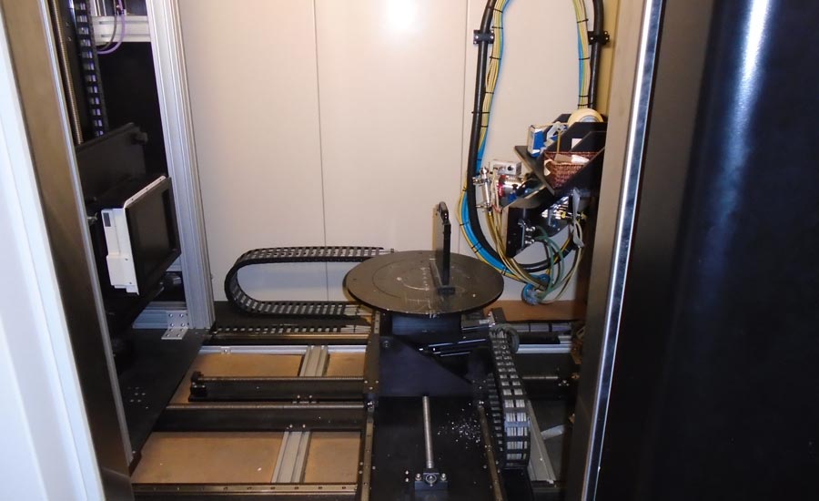
Figure 2 - DDA Set-up with 8 x 10 Detector, (left), Stage, (center) and X-Ray Tube (right). Source: Alloyweld Inspection
Digital Radiographic Advantages and Disadvantages
The primary monetary advantage of digital radiography is a dramatic reduction in consumables. Elimination of film costs, as well as the expense of chemicals, can result in a prompt return on investment. Since film development is no longer needed in the radiographic process, there is no need for the footprint of the darkroom, and the environmental issues associated with disposal of exhausted developer and fixer solutions are eliminated. Another monetary advantage is the reduction of time needed to obtain a radiographic image. Film processing normally takes around twenty-five minutes. However, DDA images are normally acquired for interpretation within ten seconds or so. Exposed CR plates need processing through a CR reader, but the typical processing time is approximately one minute.
Another advantage of digital radiographic imaging is the handling of the image itself. Test subjects are rarely just one thickness. Test subjects such as castings can have multiple thicknesses that would prompt the radiographer to use multiple speeds of film to obtain acceptable film densities with just one exposure instead of resorting to multiple exposures. A single digital image has a wide latitude such that the image reader need only to utilize the window/level computer controls to control the contrast/brightness of the region of interest. This tool enables the operator to view the relevant spectrum of gray levels in an image, maximizing the ability to see discontinuities in the relevant area. Filtering and other software capabilities offer image enhancement that increases detection capability. These software capabilities also include more accurate measurement tools than the inspector would normally use, annotation options, as well as automatic defect recognition.
Finally, radiographic film storage is eliminated with this process. Improperly processed or stored film would yellow with age, eventually degrading film as to be unreadable. Digital images retain their information indefinitely. They can be stored on a computer, disk or external hard drive that is backed up periodically. These images can also be shared on a company hard drive or emailed so that information sharing is immediate. The primary disadvantage to transitioning to digital imaging is the capital expense associated with new equipment as well as the increased training and experience required of inspection personnel. The radiographic source may be gamma or X-ray, but if X-ray is used, it is important that the generator that energizes the tube be a constant potential (high frequency) generator to reduce the production of detrimental longer wavelengths of X-ray.
The Computed Radiography (CR) Process
The CR imaging plate (IP) is exposed to radiation just like one would do with conventional film radiography. The IP can be inserted into a flexible film cassette or in a flat rigid cassette (Figure 1).
The radiographic exposure time for a CR plate is at least 50% less than a piece of film. The lifetime is determined by how they are handled and cared for. Generally speaking, flexible cassettes are used hundreds of times while rigid cassettes have been known to be used thousands of times before replacement. The IP normally consists of six layers, the heart of the imaging plate being the layer of barium fluorohalide phosphor within the plate. This phosphor is the origin of the Photo-Stimulated Luminescence (PSL) process. PSL is a physical phenomenon in which a halogenated phosphor compound emits bluish light when excited by a source of red spectrum light. In other words, phosphors capable of “PSL” exhibit a unique physical property of delayed release of visible light subsequent to radiation exposure.
Once exposed, the IP is processed through a reader, whether it be a tower (stationary) or drum (portable) style. The reader aims red light emitted from a helium neon laser at the plate which responds by emitting a bluish-purple light. The released electrons enter a digitizer that divides the analog image into squares (matrix) and assigns each square in the matrix a number based on the brightness of the square. Each square is called a picture element or pixel. The more pixels there are, the greater the image resolution. The digitization process is facilitated by computer algorithms (a string of mathematical instructions) applied that match binary pixel data with arbitrary files (called look-up tables) to assign individual pixel gray scale levels. The requirement to apply computer algorithms to the data is why this process is referred to as computed radiography. The processed image is then ready to be identified and stored. Instead of using a light viewer as in conventional film radiography, the radiographer would then read the image on a high-resolution monitor and perform the necessary evaluation according to known acceptance criteria. These monitors may be in a liquid crystal display (LCD) or light emitting diode (LED) construction with a resolution varying from 2 MP to 12 MP.
The Digital Detector Array (DDA) Radiographic Process
Flat panel detectors, known as DDAs, convert incident radiation intensity into proportional and digitized electronic signals. These digital signals can, by means of a computer and screen (workstation), without intermediate steps, be presented as a coherent radiographic image. There are four configurations of DDA panels: amorphous silicon (indirect: conversion to light, then to electronic signal); amorphous selenium (direct conversion to electronic signal); charge coupled devices (CCD), and complementary metal-oxide-semiconductor (CMOS). These rigid panels are normally used in a shielded cabinet, but portable panels that are Wi-Fi enabled are now available.
While each variation of panel has its own advantages and disadvantages compared to the others, the amorphous silicon panel is the most popular configuration within industrial NDT. In the most common composition of this panel, a scintillator made of structured Cesium Iodide (CsI) converts incident radiation directly and instantly into light. The conversion is proportional to the radiation dose. Secondly, light is converted into a proportional electric signal by thin film transistors (TFTs). Each pixel contributes to the radiographic image formed on the screen of the workstation. Each element is square in effective area, with pixel pitch typically ranging from 25 to 400 microns. The smaller the pixels, the better the resolution, but the poorer the imaging efficiency. Depending on overall active area and detector pixel pitch, a panel consists of up to several million of such elements/pixels. This panel, though relatively expensive to buy, can easily make a thousand exposures each day for five years or so if properly used. The resultant image is now treated in the same way as a CR image, to be read on a high-resolution monitor.
CONCLUSION
The choice of digital modality and equipment to facilitate a transition from conventional to digital radiography is dependent upon many factors. As with anything electronic in nature, the equipment continues to get better and less expensive. Conventional radiography will continue to have a place in NDT, but digital radiography is the future.
George Hopman is an ASNT Level III in MT, PT, ET, RT, UT, VT, MFL.
For more information, call (623) 777-1211 or [email protected].
Looking for a reprint of this article?
From high-res PDFs to custom plaques, order your copy today!


 and Digital X-ray Inspection Services")
