Aerospace | Phased Array
Phased Array Ultrasonic Testing: A Tutorial
While PAUT is becoming a popular approach for nondestructive inspections, it is important that users understand this technology, its limitations and how it should be applied.

Source: Getty Images and Birring NDE
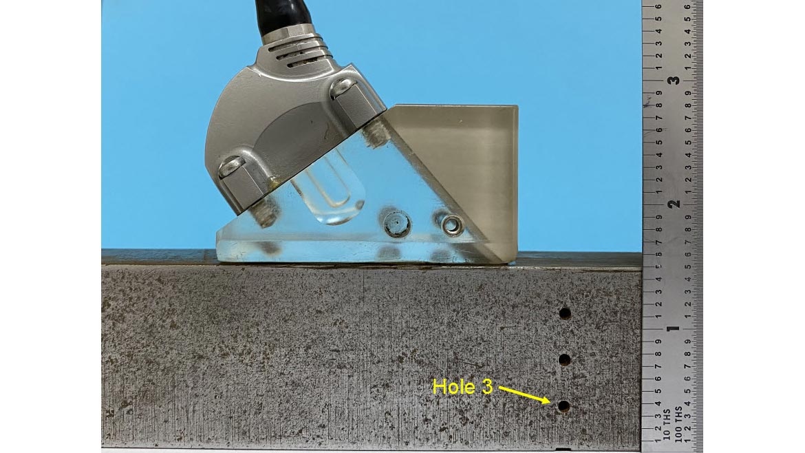
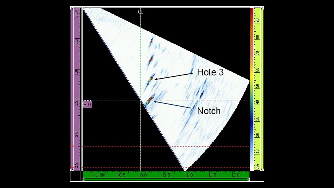
Phased array (PA), commonly referred to as ultrasound in the medical field, has been extended for industrial applications and is quickly replacing conventional angle beam ultrasonic testing (UT). While conventional ultrasonic testing utilizes single crystal probes with a fixed beam angle such as 0⁰, 45⁰, 60⁰ and 70⁰, phased array by applying time delays on multiple crystals sweeps the beam over a range of angles. This feature allows full coverage and inspection with a single phased array probe instead of multiple fixed angle probes. The time delays applied to the individual crystals are mathematically calculated to focus and sweep the beam. These are called focal laws. Using a single PA probe instead of multiple conventional probes allows simplification of manual as well as mechanical and automated UT scanners. Another advantage of phased array ultrasonic testing over conventional ultrasound is that while conventional UT displays a time based A-scan signal, phased array UT displays a sectorial image representing cross-section of the tested part. The sectorial image is much easier to understand and interpret instead of an A-scan signal that requires plotting on a component drawing. Figure 1 shows phased array probe placed on steel block with three side drilled holes and a notch. The corresponding image shows a 1:1 relationship showing the three holes making it easier for the technician to understand and interpret. Similar displays can be seen when inspecting welds and other complex geometries.
While PAUT is becoming a popular approach for nondestructive inspections, it is important that users understand this technology, its limitations and how it should be applied.
Phased Array Abbreviations: Active Aperture, A - number of active elements x element size; element size - size of crystal; F- Focal length; f - frequency in MHz; λ - wave length; v - velocity; focal spot size = F λ/A
Probe Selection: PA probe selection is very important for phased array testing. Probe frequency and its active aperture define the focusing of the beam that in turn defines image resolution. Probes with higher frequency and larger active aperture will have sharper focus and higher resolution images. Thus, a 5 MHz 32 x 1.0 mm probe will have better resolution than a 5 MHz 32 x 0.6 mm or a 2 MHz 32 x 1.0 mm probe. And a 5MHz 16 x 1.0 mm will have the same focal spot size as the 5MHz 32 x 0.5 mm. Both have the same active aperture of 16 mm
Instrument: Phased array instrument must have the ability to pulse all the required elements of the probe. Thus, to fully use a 32 element probe, the instrument must be 32:128 minimum. When using a scanner, the instrument should have the ability to save raw data along with the position information from encoder.
Scanning: PAUT inspection can be done in manual mode or can use scanners. Scanners can be manual, push-pull, or motorized as used in automated UT. All scanners include encoder output to store position information with the raw data.
Aerospace
A Quality Special Section
Scan Coverage: Scans should show 100% coverage of the volume being inspected. Coverage does not just mean flooding the volume with sound but also assure that sound is reflected back to the probe. This is important when planar reflectors such as lack of fusion are expected. Planar flaws act like mirrors and reflect the beam based on the angle of incidence.
Calibration Blocks: When conducting code inspections, the calibration block curvature and thickness shall be as per the applicable code. For example, when conducting ASME piping inspections, curved calibration blocks shall be used for diameters less than 20 inches with calibration reflectors as specified in the ASME V, Art 4.
Reference Level: This value refers to the gain setting. Gain setting is established on calibration reflectors as required by the specification and typically adjusted to obtain 80% full screen height (FSH). For ASME inspections, gain should be set to not only obtain 80% FSH at one angle, but 80% FSH for all of the angles across the sweep angle range and the range of inspection. Therefore, if the sweep angle range is 40⁰ to 65⁰, the calibration should assure 80% FSH for each angle, and for reflectors to cover the full sound path. This process is done by following calibration steps that adjusts gain for each angle or focal law. A time corrected gain (TCG) is applied to adjust gain over the sound path range.
In conclusion, phased array UT is a powerful technique but its application requires a comprehensive understanding of its use.
Looking for a reprint of this article?
From high-res PDFs to custom plaques, order your copy today!


