Test & Inspection: Hardness Testing of Coatings
There are a wide variety of testing techniques for hardness, using different principles and reporting different scales.
All Images Source: Buehler
Hardness testing is a simple mechanical test developed to provide a quantitative measurement in a quick and efficient manner. Hardness testing is used in place of other techniques such as tensile testing. There is often good correlation to tensile strength, but requires significantly less time and effort, as well as being comparatively nondestructive.
Coatings are applied to materials for a wide variety of reasons including protection from the environment, wear resistance, and surface finish modification. They are often relatively thin, but the quality of the coating can be critical to the performance and lifetime of the coated component. A full understanding of the properties of the coating is therefore critical to quality control. Compliance checks are often carried out including thickness measurements, bond strength, continuity of interfaces, contamination and porosity among many others. Hardness testing can be a quick and effective tool for checking coating properties, especially in high volume production environments. However, selection of an appropriate approach and understanding key advantages and limitations is important to ensuring an accurate result.
The principle of hardness testing is straightforward – an indenter is pressed into the material under a known load. The degree to which the indenter penetrates the material or the resultant size of the indent is measured, and the material hardness is calculated from that. Over the years, various methods for determining hardness have been developed and include a wide range of techniques, each with associated advantages and disadvantages. The purpose of this article is not to review all techniques, but to discuss particularly the application of hardness testing to coatings, typical techniques used, best practices and special considerations to ensure accurate and repeatable results.
What Type Of Hardness Test Can We Use?
There are a wide variety of testing techniques for hardness, using different principles and reporting different scales. Conversion between hardness scales is not always reliable, as conversions depend on the material type and are generally empirical in nature. Some industries will specify a particular method, but it is preferable to select a scale that is most appropriate to your material and circumstance when possible.
For softer coatings there are several widely used manual, quick and easy approaches - mainly used as comparators. These usually involve either a controlled scratch (such as the Wolff-Wilborn method) or a load applied for a set period (such as the Buchholz or Shore methods) to create plastic deformation in the coating. Assessment of the resulting scratch or dent then gives an approximation of hardness. Although these approaches are quick, they do not always provide the accuracy or reproducibility required in quality control and are typically not suited to harder materials. They may also be unduly affected by the user, or surface characteristics of the coating. They are most often used for quick assessment of softer coatings such as polymers and paints to check reproducibility between batches. For harder materials, more complex surfaces, and for greater accuracy we will often choose more automated and controlled methods.
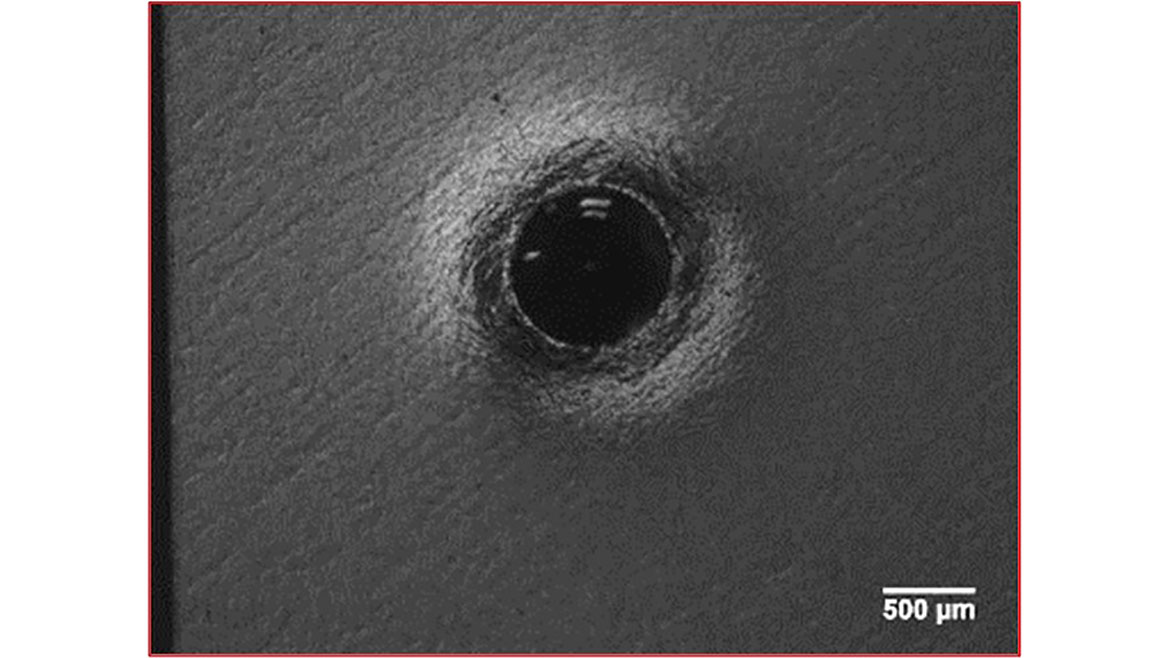
Figure 1 - Visible material deformation around a hardness indent
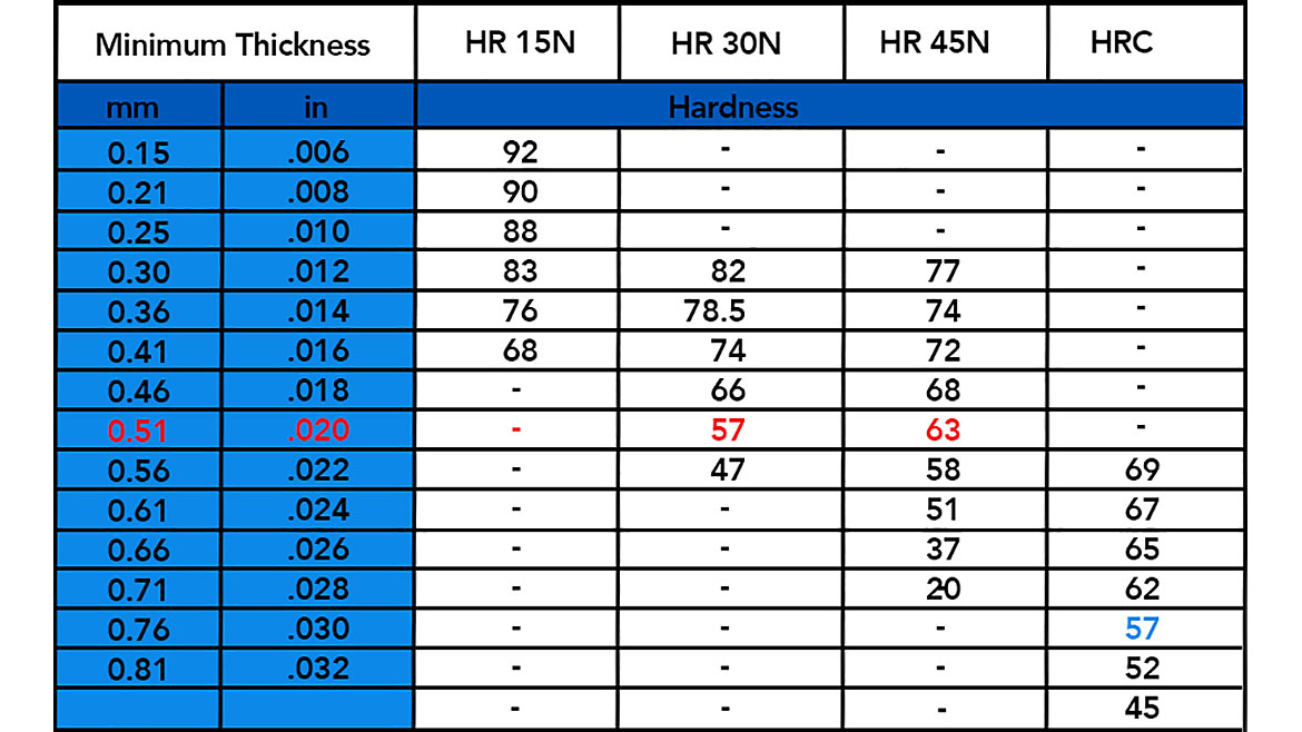
Figure 2 - Example of a minimum thickness table as found in ASTM standards
An important choice for any application is the question of whether the hardness test can be performed directly on the surface of the coating, or whether a cross-section of the coating needs to be made. If a coating has a relatively rough finish, the variability in contact area when applying an indent may be high compared with the total indent size. This would introduce scatter in test results. Using a higher load to create a larger indent reduces the variability, but it is important to make sure that the indent is not affected by the substrate material. The coating must also be significantly thicker than the depth of indent, each impression has an associated deformation zone (Figure 1). If this deformation zone is deeper than the coating, the resultant hardness reading will be affected by substrate hardness. Both ASTM and ISO standards provide guidance on suitable minimum thicknesses for a given test type and load, as this can be up to fifteen times the depth of the indent for some materials.
Another important aspect for testing directly on the surface of the coating is the method of measurement. Some hardness tests (such as Vickers and Knoop) use optical assessment of the indent to measure hardness. This requires a consistent, smooth and reflective surface to work effectively. Most often these methods are not best suited to testing coatings directly as applied but may be used when the coating is sufficiently thick and a higher test load can be used.
A good option for coatings that are less reflective is Rockwell testing. In this approach, the indenter is applied under a low ‘minor’ load, then a higher ‘major’ load and subsequently back to the minor load. The difference in depth between the major load and the final minor load is measured, to calculate hardness. As this approach does not require optical measurement it is suitable for a wide variety of coatings. The Rockwell test has more than 30 different measurement scales, with lower load methods known as “Superficial Rockwell.” The main limitation on testing is that the lowest ‘major’ load available is 15kg, and so indent size is relatively large. When using this approach, care should be taken to ensure that the coating is thick enough. The ASTM standards provide simple lookup tables for minimum material thickness for each scale (Figure 2). Testing on softer materials, or at higher loads, require greater minimum coating thickness. This can sometimes make this approach impractical.
An alternative to testing directly on the surface of the coating is to use metallographic preparation techniques to create a cross-section. This is typically done for coatings where surface testing is not possible or when additional analysis is required such as analysis of through-thickness hardness, for inspection of interface contamination, or for inspection of coating properties such as porosity, phase analysis or multiple layers. Most often this involves metallographic preparation of the cross-section, to create an undamaged, smooth and reflective surface for testing. This of course requires additional time and effort, but the advantage is that the prepared surface is suitable for hardness testing at much lower loads. Not only does this allow accurate testing of much thinner coatings, but in many cases variation in properties at different depths and multiple positions in the coating can also be assessed. A full review of preparation techniques is beyond the scope of this article, as specific recommendations are needed for different types of coatings - the reader is encouraged to reach out to the author for more in-depth recommendations. However, the following recommendations give good-practice guidance of the core principles.

Figure 3 - Vacuum impregnation equipment for mounting porous samples in epoxy with multiple vacuum cycles

Figure 4 - Even very small indents can be measured with a well prepared sample
Metallographic Preparation For Coatings
Cross-sectioning and metallographic preparation is a multi-step process, where the sample is sectioned perpendicular to the coating. The sectioned sample is encapsulated to support and protect it, and then subjected to a series of grinding and polishing steps prior to hardness testing. Best results are achieved when the coating is prepared flat and damage free. To ensure accurate results, there are some good practice recommendations to follow.
Sectioning: Cross-sectioning is best done using a precision sectioning device, and diamond or cubic boron nitride wafering blade. Keeping cutting loads low and making sure that the blade enters through the coating and exits the substrate, are critical to minimizing damage at this stage. Special care should be taken not to damage the coating through clamping. Mounting prior to sectioning is preferred in some cases, to ensure integrity of the coating.
Mounting: After cleaning and drying the cross-section, it should be mounted using a low viscosity epoxy. Best results are found when mounting under vacuum (Figure 3), to ensure penetration of the epoxy into cracks and voids. Multiple vacuum cycles are far more effective at ensuring penetration of the epoxy than extended times under vacuum. For particularly hard coatings, additives can be used in the epoxy to provide extra edge support through the preparation process.
Grinding and Polishing: Specific selection of metallographic preparation steps depend on the materials being prepared. However, in most cases a single grinding stage to remove sectioning damage can be used, followed by pre-polishing steps. The selection of polishing surfaces in these steps is critical. A high removal rate, woven, no nap cloth is ideal for the 9-micron stage. A medium hard woven no nap surface is used for the 3-micron stage. Using the correct surfaces ensures excellent flatness and fast preparation – each step typically takes under five minutes. If needed, a short (<2min) polish with an oxide slurry on a final polishing cloth can be used to create a fully scratch free finish. A clear, well formed indent made on well prepared material (Figure 4) greatly improves accuracy.
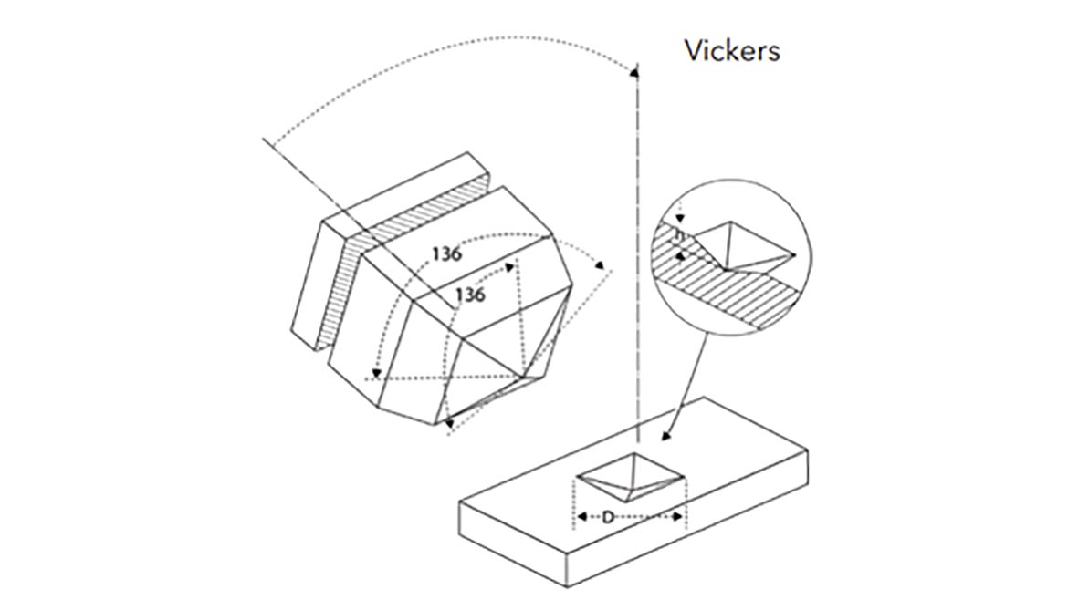
Figure 5 - The Vickers type indenter, with resulting indent
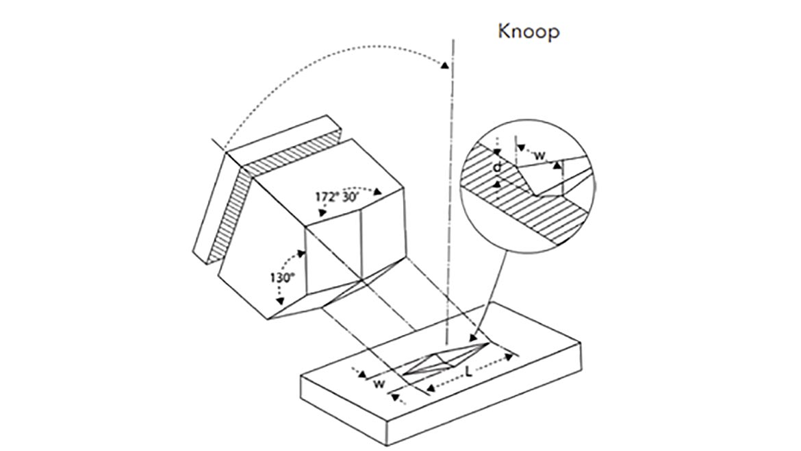
Figure 6 - The Knoop type indenter, with resulting indent
Hardness Testing On Mounted Cross-Sections
Hardness testing on prepared cross-sections is almost always done using low load optical hardness testing, such as Vickers and Knoop. As the testing is now being done perpendicular to the surface/substrate, it is important to use indents that are small enough such that the deformation zone around the indent does not interact with the boundary. As with depth restrictions, recommendations are made in both ASTM and ISO standards, and are typically 2.5-3x the width of the indent. As these methods use optical systems the indents can be accurately placed, and it is much easier to be sure of meeting these criteria.
Vickers testing uses a pyramidal diamond indenter (Figure 5) and is the most commonly used scale. However, the Knoop indenter (Figure 6) uses an elongated pyramidal shape that is both longer and shallower than the Vickers indenter. In both cases, selection of load allows very small indent sizes to be achieved. To minimize variability from optical measurement systems, indents of 20 microns or greater in the measuring diagonal are preferred. The big advantage with the Knoop indentation is that the ideal 20-micron minimum size (on the elongated diagonal, L) can be achieved, whilst the smaller width of the indenter (w) allows indents to be placed closer to edges or to each other. This is often the ideal method for measuring thin coatings, multiple layers and variation in hardness through the thickness of a coating, although typically Knoop hardness values should only be compared when made at the same load.
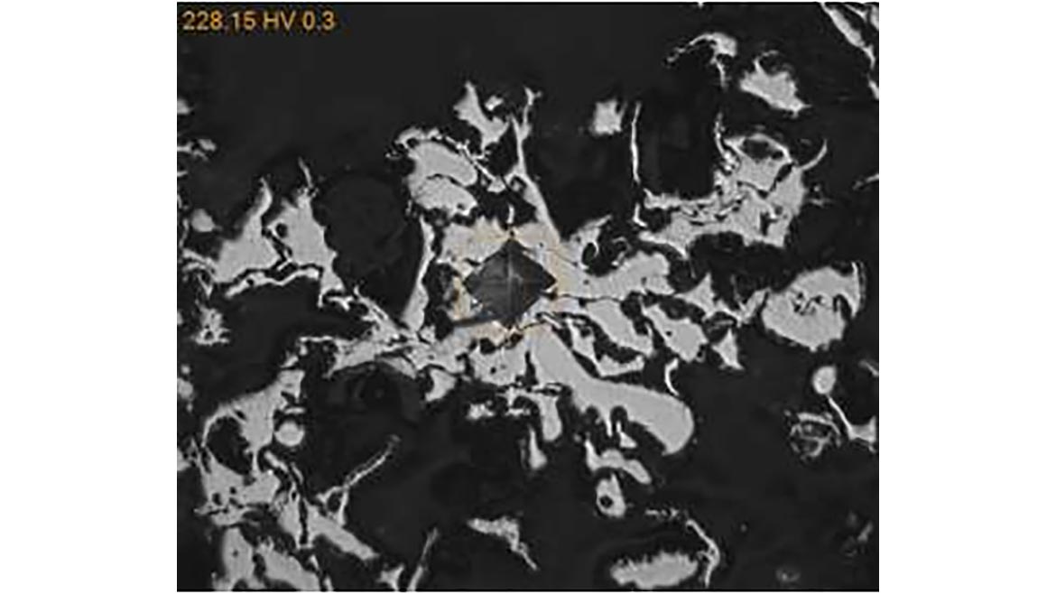
Figure 7 - Abradable coating, showing difficult placement of HV0.3 indent
Some coatings are not homogeneous and may contain multiple phases or porosity. Even as a cross-section, these coatings can be difficult to assess with small, visually measured indents. Figure 7 shows such a coating, with a Vickers indent carefully placed inside a smooth, reflective area. To test in this way would be time consuming, and still likely have significant variability, as the volume around the indent is not constant. In these cases, a Superficial Rockwell test is preferred. Faster testing would allow a larger number of indents to be made in the same amount of time, and the bigger indent size will reduce variability in test results.
Looking for a reprint of this article?
From high-res PDFs to custom plaques, order your copy today!


