Software
Software helps see inside a lights out process
Remote oversight supports processes that cannot by nature be closed loop controlled.

All Images Source: Digital Metrology Solutions
An Industry 4.0 mindset and a “lights-out” style of operation is driving quality and manufacturing teams to integrate measurements and process controls more tightly. The hope is that localized, closed loops will provide great benefits, including lower manufacturing costs, lower labor costs, and improved product quality.
But while these changes can indeed offer many benefits, getting there is not always straightforward. There is a potential to assume that, with some effort, closed loop controls can be developed for all operations and all drawing specifications. After all, what’s the point of “lights out” if you can’t turn all of the lights off for a given process? As is typically the case, the full solution is more complicated.
When closed loop feedback is simple, and when it is difficult
Some types of processes and measurements lend themselves to tight, closed loop control. Diameter, length, max thickness, etc., are one-dimensional specifications. As such, they can be associated with a single machine control, making them relatively easy to control closed loop. If a linear dimension measures too long, say, the tool depth or position can be directly adjusted to correct it.
But for other critical measurements, the relationship is not as simple. “I had a client who needed to control cylindricity, but he lamented that there isn’t a “cylindricity” knob to turn when that measured value went out of tolerance,” said Mark Malburg, president of Digital Metrology Solutions. “When it comes to flatness, roundness, roughness, waviness, etc., we may not have the simple relationships that we need to create control loops.”
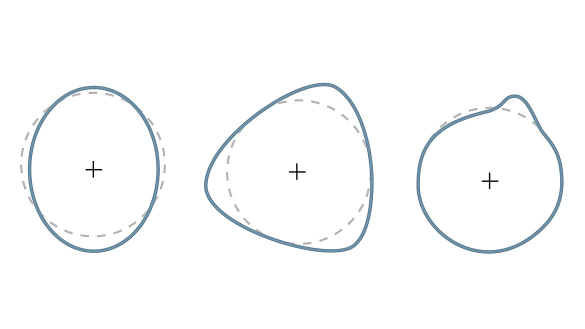
As an example, Figure 1 shows three out-of-round conditions of the same magnitude. All three shapes give the same roundness value. Each of the three roundness conditions will require unique adjustments, and the roundness number cannot describe the deviations in shape adequately enough to automatically adjust the process. The roundness value alone does not directly translate to which specific adjustment is required.
Closed loop control of surface texture can be even more challenging. Surface texture describes the shape of the surface, and it is comprised of a spectrum of shapes of varying sizes. Smaller shapes (i.e., smaller spatial wavelengths) are often controlled as “roughness,” which may impact the component’s wear, friction, appearance, and other functionality. The larger shapes (longer spatial wavelengths) which are typically considered “waviness” are more related to vibration, noise, sealing, etc.
However, neither roughness nor waviness lend themselves to easy “closed loop” control. The reason is similar to the roundness example above: the parameters that we track for roughness and waviness do not translate directly to individual process controls. The parameters may relate to the surface’s function, but not to the process used to create the surface.
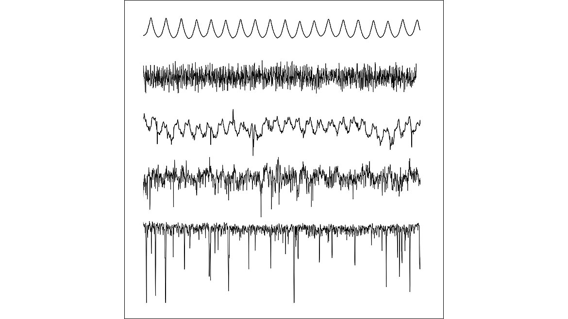
The Average Roughness (Ra) parameter, for example, is very commonly specified to control surface roughness. But, as Figure 2 shows, very different surfaces can have the same Ra value. The Ra parameter cannot distinguish peaks from valleys, wide spacings between peaks from narrow spacings, etc. Because so many surfaces can have the same Ra, it is impossible to directly relate the parameter to a specific process control. Furthermore, over time the process can begin generating surfaces with entirely different characteristics than originally intended. This drift will go unnoticed because the Ra value measures the same.
Can we apply intelligent controls to surface texture and geometry?
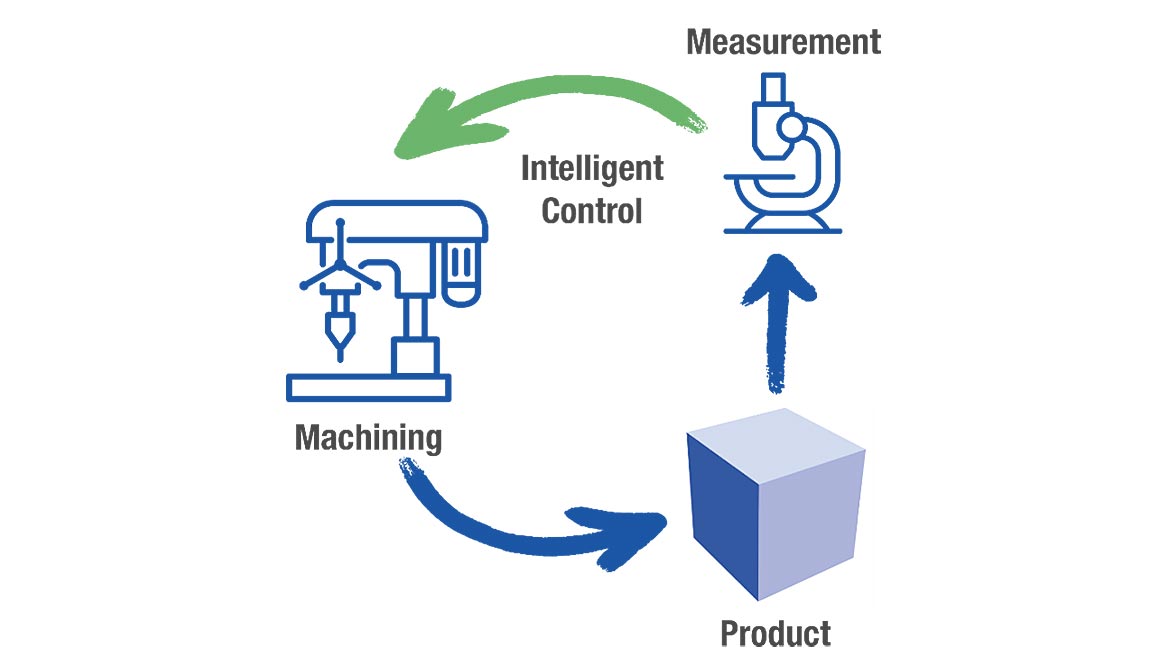
Some aspects of texture do lend themselves to closed feedback loops and intelligent control. Changes in the feedrate for a rotational process will result in a change in the spacing between the ridges left by the cutting tool. A parameter such as Rsm, which reports the spacing between roughness features, can identify these changes, and it can be used to correct the feedrate. Similarly, closed loop adjustment of stroke length and position can control aspects of cylindricity such as “taper” in a honing process. Figure 3 represents this type of workflow, where numerical results from process measurements can be used directly to adjust the process.
What we can do when closed loop is not possible
When closed loop control is not possible, says Malburg, “We need to develop opportunities for engineers and technicians to look inside the process. When personnel are stationed away from the process, they need to see the actual surface shapes that are being produced as well as the numerical SPC results in order to interpret what is happening in the process.”
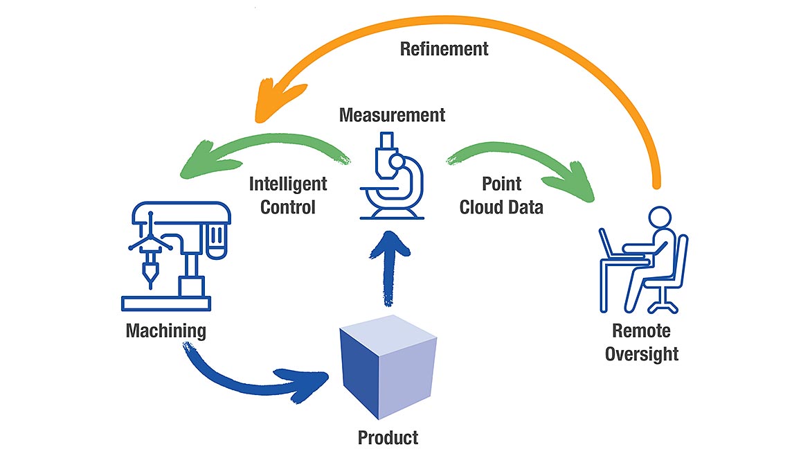
To facilitate this workflow, rather than simply collapsing the data down to numbers at the measurement instrument, measurement software can preserve the data point cloud and output it along with numerical results. When shape or texture parameters drift, an inspector, engineer, or team can examine the results to determine the corrective path—even in a lights-out environment. Figure 4 shows how the workflow changes to incorporate remote oversight.
The measurement software, however, must make it possible for users to interact with and explore the data—almost as if they are in the facility, holding and spinning the workpiece. Unfortunately, this is not always the case. “A lot of measurement software is designed to acquire data and produce a number or set of numbers, like a judge presenting a score at a sports event,” says Malburg. “It gives us limited options for understanding how that number was reached. This approach can be fine for quick production measurement, but it doesn’t help us to understand root causes and develop loops between results and controls.”
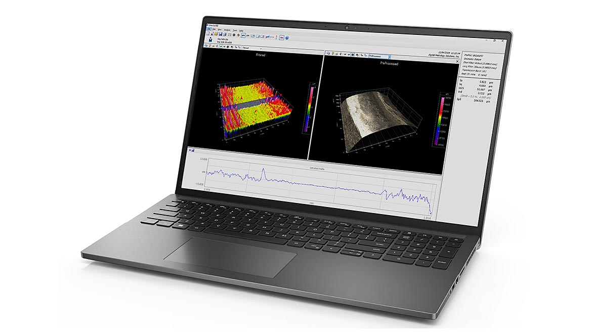
To promote that understanding, says Malburg, software needs to present the actual shapes and surfaces rather than focusing on the numerical results. For remote oversight applications, software that can help the user to visualize and interact with the workpiece makes it easier for manufacturing/process specialists to understand what is happening in a process, even when it is hundreds of miles away. Figure 5 shows an example of software in which the texture of a turned surface is presented visually in multiple, user-controlled views, along with numerical results for key parameters.
Remote oversight can help move toward closed loop control
One of the advantages of enabling remote access to point cloud data is that inspectors, designers, engineers, and even AI can interact with the data directly to uncover connections that can lead to better controls. In fact, the point cloud itself could be used for remote analysis and remote machine adjustment. Machine learning models that are fed point cloud data over time enable continuous improvement of these remote adjustments.
“When software focuses on data exploration rather than data reporting,” says Malburg, “we can better learn from the process. And what we learn can be applied to building better and better automation models.”
Product versus process considerations
Product specifications are created to ensure that the part will perform well. These specifications do not always map directly to process controls. Thus, we may need to look at measuring other aspects of the part to control the process. For example, cylindricity may be specified; however, other features such as some forms of roundness, straightness, and/or taper might be more related to process controls.
For some cases, with increased learning, we may be able to directly control the process based on the product specifications. In many cases, however, additional process-centric parameters may need to be measured in order to provide the necessary process control feedback. Ultimately, the oversight can “see inside” and provide this link between specified product features and actual process results.
Conclusion
Industry 4.0 provides an exciting opportunity and is putting a focus on manufacturing processes and their controls relative to meeting product specifications. However, not all specifications and controls are ready for Industry 4.0. In the meantime, an oversight mechanism, such as remote monitoring of raw geometry and surface information, is still required. Rather than considering this as in impediment to lights-out manufacturing, software developers can look at it as an opportunity to make measurement data more widely available beyond just measurement professionals. By promoting this layer of observation, over time, the knowledge obtained by remote monitoring may lead to further automation and improvement.
Looking for a reprint of this article?
From high-res PDFs to custom plaques, order your copy today!


