Measurement
Measuring Thickness Using Model-Based Metrology Software
Measuring and verifying the thickness of features is more critical than ever before.
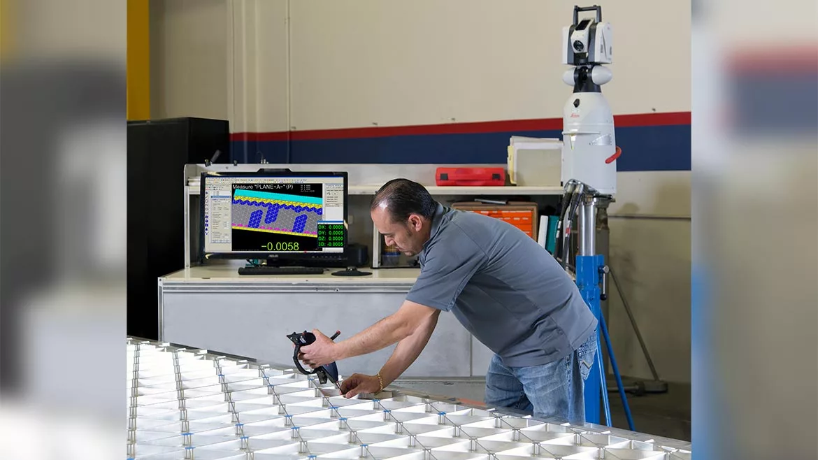
AMRO Quality Engineer Rodrigo Delgadillo inspecting flat machined grid panel wall thicknesses before forming using Verisurf inspection software and Leica laser tracker with wireless T-Probe. Source: Verisurf Software
Measuring thickness is critical in manufacturing many products to ensure quality, precision, and compliance with design specifications. Measuring thickness has evolved over time, encompassing both analog and digital devices, as well as advancements in software. Traditional calipers have been used for centuries to measure thickness manually and require a skilled operator to ensure accurate readings. Micrometers, introduced in the 17th century, provided a more precise means of measuring thickness than calipers. These mechanical devices allowed for accurate measurements in various applications and even transitioned to digital with the advent of electronics. Digital calipers and micrometers incorporated digital readouts for easier and more accurate readings.
Ultrasonic technology started being used for thickness measurements in the mid-20th century, using ultrasonic waves to determine the thickness of materials by measuring the time taken for the sound waves to travel through the material. This was a giant leap forward in technology, especially for nondestructive testing. Digital thickness gages have since become more sophisticated, incorporating data logging, statistical analysis, and improved measurement accuracy. The integration of computers in manufacturing processes allowed for more advanced thickness measurement capabilities, and software solutions were developed to analyze and store thickness data for quality control and process optimization. And so, the need and evolution of thickness measurement continues.
Today, manufacturers are making software and equipment decisions across the board based on the ability of a given solution to do more than their existing system. Floor space, resources, efficiency gains, and throughput are top-of-mind for everyone. When it comes to metrology solutions, it is no different. Software developers must stay in tune with customers’ wants and needs and deliver complete systems that will save time, increase efficiency, are easy to use, and add value to the end product. Features like Model-Based Definition (MBD), nondestructive measuring, fast and easy CMM programming, and enhanced measuring tools (including thickness) can shorten quality verification, guide tool-building, and support reverse engineering of complete parts or missing features.
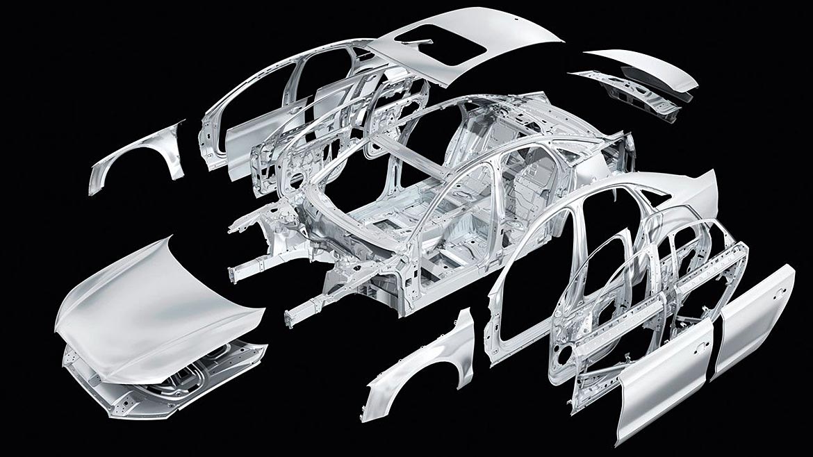
Measuring and verifying the thickness of features is more critical than ever before. Using lightweight alloys and composites in aerospace, spaceflight, automotive, and energy industries drives engineers to design parts to closer tolerances, saving every ounce of weight possible. But this can also reduce the margin of error in manufacturing, requiring close attention to quality verification of every part.
Thickness features requiring measurement or verification exist on many machined parts and assembled products, so ensuring this capability is part of your metrology software and workflow is important. Many manufacturers still use stand-alone solutions to measure things like gap, flush, step, or blind measurements that require ultrasonic measuring. This break in the digital thread is no longer necessary. Deploying a single metrology software across your manufacturing enterprise will help to consolidate workflows, improve repeatable process control, and increase quality.
One Click Thickness Measuring
Watch a software demonstration video showing one-click programming of thickness measurement in an inspection plan:
When creating an inspection routine for a portable scanner, arm, or fixed CNC CMM, one click is all it takes to include a command to measure the thickness of ribs, webs, flanges, and pockets found on many light-weighted aerospace parts. Capable model-based software will create GoTo moves, in the case of a CMM running automatic routines, to ensure proper clearance and collision avoidance.
Ultrasonic Thickness Measuring
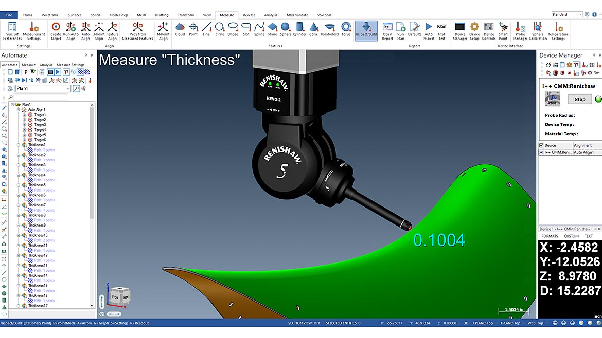
Ultrasonic technology has played a significant role in nondestructive thickness measurements. While the concept is not new, bringing the technology to a 5-axis CMM platform and integrating the measurement data with capable metrology software is innovative. An ultrasonic probe provides an ultrasonic thickness probing solution to automate the measurement and reporting of thickness requirements. With this probe, thickness evaluation is possible for typical metal parts ranging from 1mm (.039") to 20mm (.787") in thickness, with an accuracy of .01mm (.0004") on parallel surfaces and .100mm (.0039") on wedged surfaces with an angle of up to 10 degrees. Compatible metrology software can operate the CMM and collect, store, and analyze measurements as part of an overall inspection plan, providing recipients with an easy-to-read thickness map associated with the inspected component.
Measuring Step, Gap, and Flush
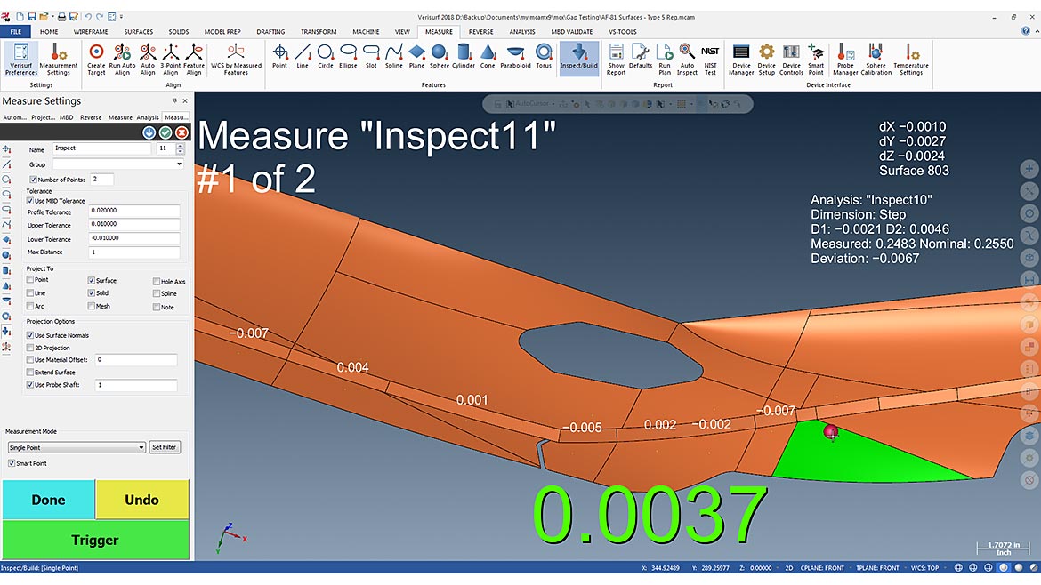
Sometimes, measuring thickness is not about measuring what is there but rather measuring what is not there, space. Advances in software have furthered the efficiency and accuracy of thickness-measuring applications, including gap, flush, and step measurements for fit and finish. Measuring the gap between adjacent surfaces, the evenness of one surface to another, or the height differences between two surfaces is critical in the automotive, aerospace, spaceflight, and energy industries. Metrology software committed to 3D Model-Based inspection can quickly and accurately inspect direct dimensions using CAD surfaces, depending on the surface normal during the measurement. If both points have similar direction normals, the software can calculate a Step; when two points have opposite facing normals, the software can calculate Thickness; and when facing each other, the software can calculate a Gap. By automating the process and using the 3D CAD model as the design nominal productivity, quality and data integrity are all improved.
RPS Alignment
RPS Alignment is used to align 3D measurement inspection data [DATA] to the reference CAD model [REF], which involves matching the measured points with nominal point values for an exact alignment. The Reference Point System is based on the full, assembled final product, such as an automobile or aircraft. RPS alignment defines how individual parts and sub-assemblies are oriented to the main reference system. The procedure is beneficial for highly contoured parts with relaxed tolerances that are required to properly mate with other parts in the assembly to get excellent gap-and-flush results. This ensures accuracy, repeatability, and consistency for all measurements and helps to eliminate ambiguities. The ultimate goal is a well-controlled alignment process that leads to higher-quality assemblies and happier customers.
When choosing enterprise metrology software, select one built on a full-featured 3D CAD/CAM platform with intelligent MBD. This will ensure flexibility and compatibility with virtually all CAD files. You will be able to work directly with customer-supplied files and perform metrology workflows in a seamless CAD/CAM environment while maintaining model-based digital continuity.
Measurement and inspection software built on a CAD/CAM platform allows intelligent GD&T data to be directly imported along with the 3D model. When the information is imported from the native CAD system as a GD&T representation, there is an accurate MBD implementation, and the authority of the dataset is preserved. The same is true if non-intelligent ‘presentation’ GD&T data is imported directly or via IGES or STEP translation and entered into the inspection application. When the product definition flows from the model through inspection and reporting, the integrity of the quality assurance process is maintained, closing the loop on design intent and implementation by feeding back to the 3D data authority.
MBD Reference Frame Example
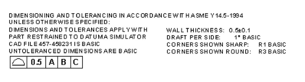
When using MBD to call out thickness, you typically use the General Profile GD&T symbol. In the case of a fixed wall thickness, for example, a note can be added to the GD&T reference frame with a tolerance for refinement of the general profile tolerance. This information and the 3D CAD model are imported directly into the metrology software to create the corresponding inspection routine.
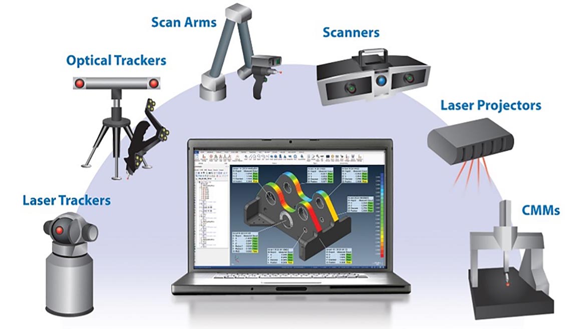
Depending on your metrology needs, your measurement software should offer inspection and reporting, reverse engineering, and support for tool building. Universal compatibility of the software to communicate with and operate all new and legacy 3D measurement devices (all types, all brands, fixed or portable) is equally important. A complete solution requires hardware (sensors) to collect measurement points; the software processes, analyzes, and presents the results.
Looking for a reprint of this article?
From high-res PDFs to custom plaques, order your copy today!


