Test & Inspection: Improve Surface Finish Measurement for Aerospace Manufacturing
The latest optical methods for measuring surfaces can be quite adept at measuring difficult to access surfaces.
 In aerospace production, surface measurement often is used for many components, including high pressure hydraulic systems and fuel injection systems. The surfaces on these components often are narrow and difficult to access, frequently residing in small o-ring grooves or at odd angles on the ends of small, difficult-to-orient parts. A wide variety of probes has been developed to measure these surfaces, but fast, accurate staging of parts-and hence, gaging throughput-remains an issue.
At the same time, the need for quality in these components is critical. Seal integrity must be absolute and mating surfaces on connectors must not damage seals. Thus, part tolerances for both form and surface finish on these components are very tight and the need for good measurement process control is rigorous.
The latest optical methods for measuring surfaces are sometimes quite adept at measuring these difficult-to-access surfaces. However, these methods have yet to be widely adopted in the aerospace industry, primarily because they are simply too new. With lives literally on the line and depending on system integrity, engineers are reluctant to risk change, and an “if it ain’t broke, don’t fix it” attitude prevails. Traditional tactile trace methods of measuring surface finish have been validated by many years of compiled data and successful use. To gain similar certitude, optical methods will no doubt have to undergo years of parallel testing to achieve the same confidence level.
Nonetheless, there are steps aerospace production engineers can take to improve the speed, accuracy and cost effectiveness of the measuring process while using traditional tactile methods. Consider three such approaches: one in which form and surface measurements are merged on a high end metrology system; a second in which parts are more efficiently staged for measurement on such a system; and a third in which the surface finish gages are customized to allow better access to the difficult to measure features on the parts. All three approaches demonstrate improved ease of use and consequent reduction in operator error, better gage repeatability and improved measurement throughput.
In that article we described how measurement data is filtered by wavelength (also known as setting the cutoff in measurement parlance). Within the limitations of a probe or stylus tip and the device used, any part trace includes an amalgam of a nearly infinite number of different wavelengths present in the path being traced. These, in turn, reflect characteristics imposed by the manufacturing process.
Traditionally, this data has been divided into three categories: roughness, waviness and form. Shorter wavelength data tends to reflect surface roughness characteristics imposed by machining operations such as turning, grinding or polishing. Waviness involves longer wavelength data and may reflect conditions caused by instabilities in the machining process, such as imbalance in a grinding wheel or worn spindle bearings. Long wavelength data tends to reflect errors such as lack of straightness in the guideways of a machine or misalignment of machine axes. These long wavelength errors are usually thought of as form characteristics such as roundness, straightness or flatness. Perfect straightness, for example, could be described as a line, or wave, with an amplitude of zero.
Since that article appeared, a number of manufacturers have introduced systems which do, in fact, provide for the measurement of both form and surface finish parameters on the same instrument, often within the same setup.
It should be noted that historically form measurement machines were designed to measure longer wavelengths, utilizing longer spacing (typically 5-10 microns) between data points and some inherent filtering of short wavelength data within the instrument. Measuring surface finish characteristics according to accepted ISO, ASME and JIS standards requires an increase in the resolution of the typical form measuring instrument and adherence to the filtering requirements of these standards.
For tricky aerospace components, such systems offer several benefits, including reduced setup and measurement cycle time. But measurements often are easier as well. High-end form testers are CNC-based, meaning they can control movement in multiple axes, even several of them simultaneously. Thus, a single setup can be used for multiple measurements. And when it comes to measuring the surface in a small o-ring groove, for example, it is much easier to accomplish the trace if the part is on a rotary table than if it is on a linear gage.
But the process can be improved. Fixturing systems are routinely designed for companies, which improve the efficiency of staging small complex parts by orders of magnitude. There is no technical wizardry involved, and these systems do not break new conceptual ground. In fact, it is rather the opposite: these systems succeed because they are based on good, solid mechanical design principles and use basic kinematic mounting techniques.
The idea is simple. For each part, one or more mounting fixtures is custom designed, depending on the number of features that need to be accessed and measured and the orientations those measurements require. These, in turn, mount in another base fixture designed to mount on the measurement machine. The operator simply puts the part in the fixture, puts the fixture in the base, presses the appropriate measurement icon on the touch screen and the system takes the measurement.
But while the idea is simple, the implementation requires careful design and planning. In order to be fail-safe, these fixtures must be designed- insofar as it is possible-such that the operator cannot put the part in the fixture wrong and cannot mount the fixture into the base wrong. The ultimate goal is to create a solution that requires no tools for mounting the part in the fixture and none for placing the fixture on the machine. The fixture should be designed in such a way as to ensure that the part is firmly held once it is inserted into the fixture and the holding force is operator independent. Typically this is accomplished with springs to set the holding force. This ensures that the part is always firmly held and the operator cannot forget to tighten some clamping mechanism. Furthermore the clamping force is controlled so that nothing can be over-tightened and distort the part for measurement.
Such fixturing systems are the best way to ensure reliable functionality in a production environment. By using them, operators can make highly sophisticated form and surface finish measurements quickly, easily, and most importantly, accurately.
There are several rules for the design of such systems. First, in addition to shop-hardening the gage, the design must protect sensitive probe and drive components. It must allow access to the features to be measured. It must be designed to eliminate operator error as much as possible, and of course, it must be fast and easy to use.
One approach has been to develop a series of modular fixtures, keyed to the requirements of specific components, that enable operators to simply place the fixture in the area to be measured, and with the touch of a single button or two, affect the entire measurement process. The fixture itself takes care of accurately positioning the gage, engaging the probe and taking and recording the measurement.
A good example of this is the measurement of surface roughness in bores. This often is difficult due to the size and depth of the bore. Typically, positioning the drive unit often leads to probe damage and drive unit positioning problems. The bore fixtures were designed to eliminate these problems by automatically positioning the measurement probe in the correct orientation.
In one example, a dedicated bore fixture, mounted on the front of the handle assembly, accurately positions the probe in the area to be measured. During entry into the bore, the probe is in a protected position. A mechanical device allows the probe to drop into measurement position only when the plug is fully seated against the front of the bore. No operator technique is required for orientation or protection of the measurement probe.
Thus, by a combination of merging form and surface finish measurement, efficiently staging small complex components using intelligent fixturing, or designing gages that more efficiently measure parts directly, traditional tactile methods of surface finish can be employed more quickly and efficiently, and even with improved accuracy. Q
The ultimate goal is to create a solution that requires no tools for mounting the part in the fixture and none for placing the fixture on the machine.
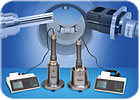
There are many applications where it makes more sense to measure parts directly wherever they are rather than take them into a metrology lab or mount them on a gaging system.
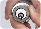
The measurement of surface roughness in bores often is difficult due to the size and depth of the bore. In this example, a dedicated bore fixture, mounted on the front of the handle assembly, accurately positions the probe in the area to be measured. During entry into the bore, the probe is in a protected position. A mechanical device allows the probe to drop into measurement position only when the plug is fully seated against the front of the bore. No operator technique is required for orientation or protection of the measurement probe. Source: Mahr Federal
There are many applications where it makes more sense to measure parts directly rather than take them into a metrology lab or mount them on a gaging system. There are several rules for the design of such systems. First, in addition to shop-hardening the gage, the design must protect sensitive probe and drive components. Source: Mahr Federal
At the same time, the need for quality in these components is critical. Seal integrity must be absolute and mating surfaces on connectors must not damage seals. Thus, part tolerances for both form and surface finish on these components are very tight and the need for good measurement process control is rigorous.
The latest optical methods for measuring surfaces are sometimes quite adept at measuring these difficult-to-access surfaces. However, these methods have yet to be widely adopted in the aerospace industry, primarily because they are simply too new. With lives literally on the line and depending on system integrity, engineers are reluctant to risk change, and an “if it ain’t broke, don’t fix it” attitude prevails. Traditional tactile trace methods of measuring surface finish have been validated by many years of compiled data and successful use. To gain similar certitude, optical methods will no doubt have to undergo years of parallel testing to achieve the same confidence level.
Nonetheless, there are steps aerospace production engineers can take to improve the speed, accuracy and cost effectiveness of the measuring process while using traditional tactile methods. Consider three such approaches: one in which form and surface measurements are merged on a high end metrology system; a second in which parts are more efficiently staged for measurement on such a system; and a third in which the surface finish gages are customized to allow better access to the difficult to measure features on the parts. All three approaches demonstrate improved ease of use and consequent reduction in operator error, better gage repeatability and improved measurement throughput.
There are many applications where it makes more sense to measure parts directly rather than take them into a metrology lab or mount them on a gaging system. There are several rules for the design of such systems. First, in addition to shop-hardening the gage, the design must protect sensitive probe and drive components. Source: Mahr Federal
Merging Form and Surface
We have written before (Quality Magazine, September 2006) that, while there are often fundamental differences in the design and manufacture between instruments that measure form and those that measure surface finish, the only real difference between the measurements themselves is the frequency or wavelength of the data set used.In that article we described how measurement data is filtered by wavelength (also known as setting the cutoff in measurement parlance). Within the limitations of a probe or stylus tip and the device used, any part trace includes an amalgam of a nearly infinite number of different wavelengths present in the path being traced. These, in turn, reflect characteristics imposed by the manufacturing process.
Traditionally, this data has been divided into three categories: roughness, waviness and form. Shorter wavelength data tends to reflect surface roughness characteristics imposed by machining operations such as turning, grinding or polishing. Waviness involves longer wavelength data and may reflect conditions caused by instabilities in the machining process, such as imbalance in a grinding wheel or worn spindle bearings. Long wavelength data tends to reflect errors such as lack of straightness in the guideways of a machine or misalignment of machine axes. These long wavelength errors are usually thought of as form characteristics such as roundness, straightness or flatness. Perfect straightness, for example, could be described as a line, or wave, with an amplitude of zero.
Since that article appeared, a number of manufacturers have introduced systems which do, in fact, provide for the measurement of both form and surface finish parameters on the same instrument, often within the same setup.
It should be noted that historically form measurement machines were designed to measure longer wavelengths, utilizing longer spacing (typically 5-10 microns) between data points and some inherent filtering of short wavelength data within the instrument. Measuring surface finish characteristics according to accepted ISO, ASME and JIS standards requires an increase in the resolution of the typical form measuring instrument and adherence to the filtering requirements of these standards.
For tricky aerospace components, such systems offer several benefits, including reduced setup and measurement cycle time. But measurements often are easier as well. High-end form testers are CNC-based, meaning they can control movement in multiple axes, even several of them simultaneously. Thus, a single setup can be used for multiple measurements. And when it comes to measuring the surface in a small o-ring groove, for example, it is much easier to accomplish the trace if the part is on a rotary table than if it is on a linear gage.
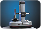
A number of manufacturers have introduced systems which provide for the measurement of both form and surface finish parameters on the same instrument, often within the same setup. This model samples data with spacing as tight as 0.005 micron-far exceeding accepted international standards for roughness measurement-and is more robust, less sensitive to environmental influences, faster, more flexible and more accurate for use in production environments. Source: Mahr Federal
Kinematic Staging Improves Efficiency
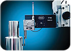
Combining form and surface can reduce the number of required setups and improve the measurement process, but staging small complex parts remains difficult. If you have a plunger about the size of a pen, for example, with a small groove on its side about 1 millimeter across, and it has to be staged in a particular orientation and at a precise angle to run a surface finish trace along the bottom of the groove, the setup is going to require an experienced operator, it is going to take time, and it is going to be prone to measurement error.But the process can be improved. Fixturing systems are routinely designed for companies, which improve the efficiency of staging small complex parts by orders of magnitude. There is no technical wizardry involved, and these systems do not break new conceptual ground. In fact, it is rather the opposite: these systems succeed because they are based on good, solid mechanical design principles and use basic kinematic mounting techniques.
The idea is simple. For each part, one or more mounting fixtures is custom designed, depending on the number of features that need to be accessed and measured and the orientations those measurements require. These, in turn, mount in another base fixture designed to mount on the measurement machine. The operator simply puts the part in the fixture, puts the fixture in the base, presses the appropriate measurement icon on the touch screen and the system takes the measurement.
But while the idea is simple, the implementation requires careful design and planning. In order to be fail-safe, these fixtures must be designed- insofar as it is possible-such that the operator cannot put the part in the fixture wrong and cannot mount the fixture into the base wrong. The ultimate goal is to create a solution that requires no tools for mounting the part in the fixture and none for placing the fixture on the machine. The fixture should be designed in such a way as to ensure that the part is firmly held once it is inserted into the fixture and the holding force is operator independent. Typically this is accomplished with springs to set the holding force. This ensures that the part is always firmly held and the operator cannot forget to tighten some clamping mechanism. Furthermore the clamping force is controlled so that nothing can be over-tightened and distort the part for measurement.
Such fixturing systems are the best way to ensure reliable functionality in a production environment. By using them, operators can make highly sophisticated form and surface finish measurements quickly, easily, and most importantly, accurately.
Taking the Gage to the Part
While most of the focus in the preceding examples has been on small, easily transported parts, there are many applications where it makes more sense to measure parts directly wherever they are rather than take them into a metrology lab or mount them on a gaging system.There are several rules for the design of such systems. First, in addition to shop-hardening the gage, the design must protect sensitive probe and drive components. It must allow access to the features to be measured. It must be designed to eliminate operator error as much as possible, and of course, it must be fast and easy to use.
One approach has been to develop a series of modular fixtures, keyed to the requirements of specific components, that enable operators to simply place the fixture in the area to be measured, and with the touch of a single button or two, affect the entire measurement process. The fixture itself takes care of accurately positioning the gage, engaging the probe and taking and recording the measurement.
A good example of this is the measurement of surface roughness in bores. This often is difficult due to the size and depth of the bore. Typically, positioning the drive unit often leads to probe damage and drive unit positioning problems. The bore fixtures were designed to eliminate these problems by automatically positioning the measurement probe in the correct orientation.
In one example, a dedicated bore fixture, mounted on the front of the handle assembly, accurately positions the probe in the area to be measured. During entry into the bore, the probe is in a protected position. A mechanical device allows the probe to drop into measurement position only when the plug is fully seated against the front of the bore. No operator technique is required for orientation or protection of the measurement probe.
Thus, by a combination of merging form and surface finish measurement, efficiently staging small complex components using intelligent fixturing, or designing gages that more efficiently measure parts directly, traditional tactile methods of surface finish can be employed more quickly and efficiently, and even with improved accuracy. Q
Benefits
Combining form and surface can reduce the number of required setups and improve the measurement process, but staging small complex parts remains difficult.The ultimate goal is to create a solution that requires no tools for mounting the part in the fixture and none for placing the fixture on the machine.
There are many applications where it makes more sense to measure parts directly wherever they are rather than take them into a metrology lab or mount them on a gaging system.
Looking for a reprint of this article?
From high-res PDFs to custom plaques, order your copy today!


