Case Study: Putting It All on the Line
Matrox Imaging smart camera provides the vision for engine assembly and test system.

ThyssenKrupp System Engineering Inc. is a world leader in the design and manufacture of turn-key assembly and test systems for automotive powertrain components, including engines, transmissions, and axles.
A manufacturer of construction and heavy equipment recently commissioned ThyssenKrupp System Engineering (Auburn Hills, MI) to build an engine assembly line for a new plant in the U.S. Southwest. In addition to its role as a line builder, ThyssenKrupp had the mandate to provide this factory with a machine vision solution for the entire engine assembly line. Acting as the system integrator, ThyssenKrupp supplied the vision, mechanical and electrical systems, Programmable Logic Controller (PLC) connectivity, and training of plant staff. The first steps of the vision solution were developed using six Matrox Iris GT smart cameras. As an engine moves down the line, it goes through multiple smart camera-based vision inspection stations. These applications vary from absence/presence to gauging/measurement.
The addition of machine vision to the line came about when the customer expressed concern with the final test machines failing engines due to operator errors during assembly. ThyssenKrupp presented a camera-based solution similar to what they had developed in the past for other engine builders. This solution would use vision inspection at the station where the parts were being installed. Any errors would then be fixed at the assembly station.
ThyssenKrupp Program Manager Pat Coughlin explains, “Working with the customer, we determined that the part complexity, combined with the extensive teardown and rework required if an error is made, justified the use of in-station inspection. A camera was a perfect fit because it can handle the part variation and can be located completely out of the operator’s workspace.”
Application A uses one Matrox Iris GT smart camera to verify that the crank gear and water pump gear are aligned properly. The crank gear has a carrot feature and the water pump gear has a painted yellow line. The yellow line must be pointing at the carrot.
Application B uses four Matrox Iris GTs. Cameras 1 and 2 both verify the presence and location of eight water seals. Camera 3 determines the presence and location of a drainback seal, another gasket, and eight water seals. Camera 4 verifies that only a single head gasket is installed.
Application C uses a single Matrox Iris GT to verify that the timing mark (painted line) on the idler gear is between two painted teeth on the crank gear.
A Siemens Human Machine Interface (HMI) panel is located at each assembly station. It provides the operator with the engine build type, cycle time display and any specific information required at that station. The HMI also displays the camera image so that the operator can look at the inspection in the event of a failure. He then identifies the object that failed and takes corrective action. The network connection is used for communication with the same Siemens PLC that runs the entire assembly line using the TCP/IP protocol. The camera acts as a server and the PLC is the client. The camera monitors the connection from the PLC and if the connection terminates, the camera automatically makes the communication port once again available for the PLC to reconnect. The PLC is also responsible for sending the proper recipes to the camera depending upon the engine type in station.
In addition to building a flowchart, the IDE lets users directly design a graphical operator interface to the application, which presents the inspected image as well as inspection statistics and controls. The operator interface displays annotations and pass/fail statistics. No control was given in the operator interface that would allow changes to be made to the project.
A number of Design Assistant tools or flowchart steps were used. “Image processing operations enhanced and transformed images in preparation for subsequent analysis,” says ThyssenKrupp Controls Engineer Matthew Maitland. “As well, objects were analyzed using image intensity. Measurement tools, which are used to assess parts’ manufacturing quality, performed 2D geometric dimensioning and tolerancing. The metrology step was used for identifying features and to take measurements between them. For example, angle of crank was verified as ‘top-dead center’ using angle between center of crank and ’arrow’ pattern. The measurement step was used for Application B - Camera 4 to determine the thickness of the head gasket. A variety of tools were used for redundant detection of features so if one tool failed, a secondary tool would be used for detection. The pattern matching step, as well as the model finder tools-which locate objects using their geometric features-were used, depending on the object, for both fixturing and object detection/measurement.”
Design Assistant’s subflowchart feature allows the inspection logic to be neatly separated from the communication and data logging logic. This helped simplify the design process and will facilitate future maintenance. Subflowcharts allow for a common programming architecture between cameras with the main program and custom subflowcharts for different program numbers/complexity. The subflowcharts contain only vision tools, which make it easy to troubleshoot when complex modifications are required.
Other smart cameras were evaluated by ThyssenKrupp for the vision system but the Matrox Iris GT offered some key advantages. Maitland explains, “Matrox products offer features best suited for this application at a competitive price.” He continues, “Matrox Iris GT also has a lot more memory than other smart cameras. We can load multiple jobs (inspections) in memory simultaneously. Other smart cameras’ memory limitations would have required that we load one job at a time. As well, images would have to be stored on a separate PC, since there would be inadequate on-camera storage. Design Assistant’s flowchart logic also allows us to branch and execute different inspections within an application. In contrast, other smart cameras only support the development of standalone inspections-an application needs to be shut down before the next one can be loaded and executed.”
The engine line’s vision system was deployed in September 2010. “Deployment went smoothly,” explains Maitland. “Application troubleshooting was handled remotely-it’s easy to debug a flowchart when the logic is visually presented as interconnected blocks.” ThyssenKrupp handled the majority of these technical issues and only required support from Matrox Imaging on a few occasions during the initial development phase. It was on those rare occasions, however, that ThyssenKrupp appreciated having direct access to experienced engineers at Matrox. Fabio Perelli, Smart Camera Product Manager for Matrox Imaging, adds, “ThyssenKrupp vision developers are extremely experienced-in fact, they provided us with valuable feedback on our smart camera software-some of which has already been incorporated into Matrox Design Assistant.”
As well, ThyssenKrupp only needed to spend a day training plant staff on the vision system. And so far, there have been no technical issues that have required ThyssenKrupp to send staff on-site to troubleshoot.
Moving forward
Three inspection stations on the engine assembly line currently use vision and another station was added in January 2011. Since the first three stations have proven to be effective and maintenance-free, the engine manufacturer is looking to use Matrox Imaging vision components to ensure that many more assembly processes are being completed properly.
Matrox Imaging
(800) 804-6243
www.matrox.com/imaging
In addition to building a flowchart, the IDE lets users directly design a graphical operator interface to the application, which presents the inspected image as well as inspection statistics and controls.
Design Assistant’s subflowchart feature allows the inspection logic to be neatly separated from the communication and data logging logic.
A manufacturer of construction and heavy equipment commissioned ThyssenKrupp Engineering to build an engine assembly line for a new plant. In addition to its role as a line builder, ThyssenKrupp had the mandate to provide this factory with a machine vision solution for the line. Source: ThyssenKrupp System engineering Inc.
ThyssenKrupp System Engineering Inc. is a world leader in the design and manufacture of turn-key assembly and test systems for automotive powertrain components, including engines, transmissions, and axles.
A manufacturer of construction and heavy equipment recently commissioned ThyssenKrupp System Engineering (Auburn Hills, MI) to build an engine assembly line for a new plant in the U.S. Southwest. In addition to its role as a line builder, ThyssenKrupp had the mandate to provide this factory with a machine vision solution for the entire engine assembly line. Acting as the system integrator, ThyssenKrupp supplied the vision, mechanical and electrical systems, Programmable Logic Controller (PLC) connectivity, and training of plant staff. The first steps of the vision solution were developed using six Matrox Iris GT smart cameras. As an engine moves down the line, it goes through multiple smart camera-based vision inspection stations. These applications vary from absence/presence to gauging/measurement.
The addition of machine vision to the line came about when the customer expressed concern with the final test machines failing engines due to operator errors during assembly. ThyssenKrupp presented a camera-based solution similar to what they had developed in the past for other engine builders. This solution would use vision inspection at the station where the parts were being installed. Any errors would then be fixed at the assembly station.
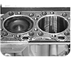
Two Matrox Iris GT smart cameras verify the presence and location of eight water seals. Source: ThyssenKrupp System engineering Inc.
Adding Vision to the Engine Line
The heavy equipment manufacturer was a brand new ThyssenKrupp System Engineering customer who was skeptical about using vision-based inspection as part of their assembly line. The manufacturer questioned the reliability of the results, and had concerns about the dependability and maintainability of vision.ThyssenKrupp Program Manager Pat Coughlin explains, “Working with the customer, we determined that the part complexity, combined with the extensive teardown and rework required if an error is made, justified the use of in-station inspection. A camera was a perfect fit because it can handle the part variation and can be located completely out of the operator’s workspace.”
Application A uses one Matrox Iris GT smart camera to verify that the crank gear and water pump gear are aligned properly. The crank gear has a carrot feature and the water pump gear has a painted yellow line. The yellow line must be pointing at the carrot.
Application B uses four Matrox Iris GTs. Cameras 1 and 2 both verify the presence and location of eight water seals. Camera 3 determines the presence and location of a drainback seal, another gasket, and eight water seals. Camera 4 verifies that only a single head gasket is installed.
Application C uses a single Matrox Iris GT to verify that the timing mark (painted line) on the idler gear is between two painted teeth on the crank gear.
Smart-Camera-Based Vision Inspection
The vision system is based on several Matrox Iris GT smart cameras. The applications were developed with Matrox Design Assistant, an integrated development environment that is bundled with the smart camera. Matrox Design Assistant is an integrated development environment (IDE) that lets users create machine vision applications by constructing a flowchart instead of coding programs or scripts using languages like Visual Basic, C, C++ or C#. Once development is finished, the project (or flowchart) is uploaded and stored locally on the Matrox Iris GT. The project is then executed on the smart camera without the need for any companion PC and, in this case, is monitored and controlled from the PLC over an Ethernet link.A Siemens Human Machine Interface (HMI) panel is located at each assembly station. It provides the operator with the engine build type, cycle time display and any specific information required at that station. The HMI also displays the camera image so that the operator can look at the inspection in the event of a failure. He then identifies the object that failed and takes corrective action. The network connection is used for communication with the same Siemens PLC that runs the entire assembly line using the TCP/IP protocol. The camera acts as a server and the PLC is the client. The camera monitors the connection from the PLC and if the connection terminates, the camera automatically makes the communication port once again available for the PLC to reconnect. The PLC is also responsible for sending the proper recipes to the camera depending upon the engine type in station.
In addition to building a flowchart, the IDE lets users directly design a graphical operator interface to the application, which presents the inspected image as well as inspection statistics and controls. The operator interface displays annotations and pass/fail statistics. No control was given in the operator interface that would allow changes to be made to the project.
A number of Design Assistant tools or flowchart steps were used. “Image processing operations enhanced and transformed images in preparation for subsequent analysis,” says ThyssenKrupp Controls Engineer Matthew Maitland. “As well, objects were analyzed using image intensity. Measurement tools, which are used to assess parts’ manufacturing quality, performed 2D geometric dimensioning and tolerancing. The metrology step was used for identifying features and to take measurements between them. For example, angle of crank was verified as ‘top-dead center’ using angle between center of crank and ’arrow’ pattern. The measurement step was used for Application B - Camera 4 to determine the thickness of the head gasket. A variety of tools were used for redundant detection of features so if one tool failed, a secondary tool would be used for detection. The pattern matching step, as well as the model finder tools-which locate objects using their geometric features-were used, depending on the object, for both fixturing and object detection/measurement.”
Design Assistant’s subflowchart feature allows the inspection logic to be neatly separated from the communication and data logging logic. This helped simplify the design process and will facilitate future maintenance. Subflowcharts allow for a common programming architecture between cameras with the main program and custom subflowcharts for different program numbers/complexity. The subflowcharts contain only vision tools, which make it easy to troubleshoot when complex modifications are required.
Other smart cameras were evaluated by ThyssenKrupp for the vision system but the Matrox Iris GT offered some key advantages. Maitland explains, “Matrox products offer features best suited for this application at a competitive price.” He continues, “Matrox Iris GT also has a lot more memory than other smart cameras. We can load multiple jobs (inspections) in memory simultaneously. Other smart cameras’ memory limitations would have required that we load one job at a time. As well, images would have to be stored on a separate PC, since there would be inadequate on-camera storage. Design Assistant’s flowchart logic also allows us to branch and execute different inspections within an application. In contrast, other smart cameras only support the development of standalone inspections-an application needs to be shut down before the next one can be loaded and executed.”
The engine line’s vision system was deployed in September 2010. “Deployment went smoothly,” explains Maitland. “Application troubleshooting was handled remotely-it’s easy to debug a flowchart when the logic is visually presented as interconnected blocks.” ThyssenKrupp handled the majority of these technical issues and only required support from Matrox Imaging on a few occasions during the initial development phase. It was on those rare occasions, however, that ThyssenKrupp appreciated having direct access to experienced engineers at Matrox. Fabio Perelli, Smart Camera Product Manager for Matrox Imaging, adds, “ThyssenKrupp vision developers are extremely experienced-in fact, they provided us with valuable feedback on our smart camera software-some of which has already been incorporated into Matrox Design Assistant.”
As well, ThyssenKrupp only needed to spend a day training plant staff on the vision system. And so far, there have been no technical issues that have required ThyssenKrupp to send staff on-site to troubleshoot.
Moving forward
Three inspection stations on the engine assembly line currently use vision and another station was added in January 2011. Since the first three stations have proven to be effective and maintenance-free, the engine manufacturer is looking to use Matrox Imaging vision components to ensure that many more assembly processes are being completed properly.
Matrox Imaging
(800) 804-6243
www.matrox.com/imaging
Benefits
The camera-based solution uses vision inspection at the station where the parts were being installed and any errors would then be fixed at the assembly station.In addition to building a flowchart, the IDE lets users directly design a graphical operator interface to the application, which presents the inspected image as well as inspection statistics and controls.
Design Assistant’s subflowchart feature allows the inspection logic to be neatly separated from the communication and data logging logic.
Looking for a reprint of this article?
From high-res PDFs to custom plaques, order your copy today!


