3-D Vision
Addressing challenging manufacturing inspection applications.
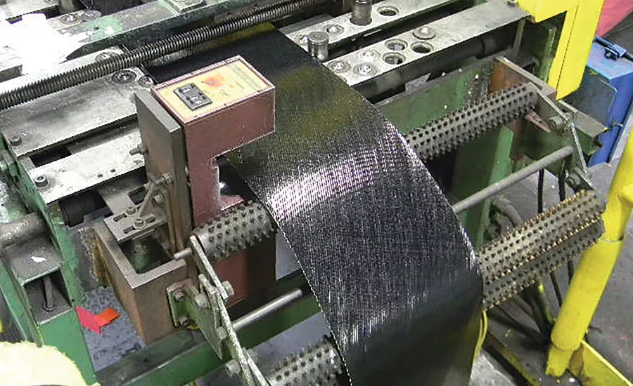
Inspection of tire body plies. Source: Cognex
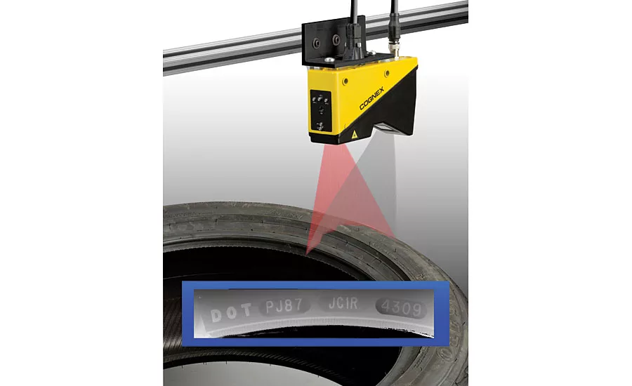
Contrast variant inspection of tire codes. Source: Cognex
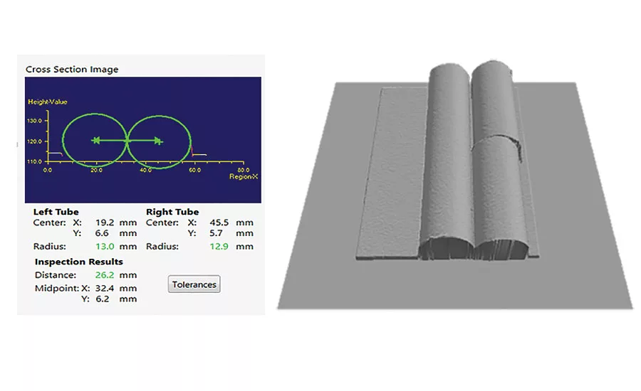
3D position and measurement example. Source: Cognex
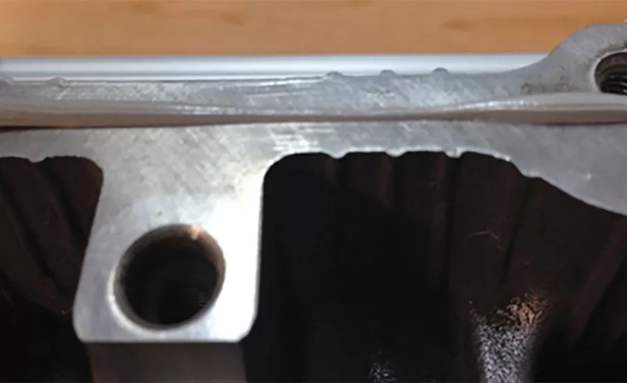
Sealant bead applied to control module housing Source: Cognex
Parts that are curved and free to move during inspection present special challenges. Source: Cognex
3D vision system measures volume of bead. Source: Cognex
3D vision systems are being implemented throughout a number of inspection applications that previously could not be addressed with conventional 2D vision systems. One such 3D system is a laser displacement sensor, which consists of a laser that projects a line and an image sensor, which are both contained in an industrial housing. The object to be measured is moved through the projected laser line and the image sensor captures the displacement of that laser line to extract a three dimensional point cloud of data. This point cloud of data can be used to measure 3D features such as length, width, height, tilt, or volume. It can be used to detect defects, the presence and absence of specific features, or read raised or embossed characters against a low-contrast background. To assist with the extra layer of complexity that 3D inspection brings to machine vision programming, 3D vision programming environments have been upgraded to simplify the process for building maintainable 3D vision applications.
As an example, consider the automotive tire manufacturing process. In the traditional manual inspection process, operators inspect the splice visually and by taking measurements with calipers at regular intervals. The problem with this sampling approach is that problems are often intermittent, which means that a considerable amount of time can elapse before a problem is detected. Even when the operator detects a problem, he or she has no way of knowing whether this is the first or 100th time that it has occurred. Common defects that frequently go undetected include out-of-spec variations in thickness, width and step-height as well as holes, and extra or missing material. A 3D vision system, on the other hand, can detect every defect and it can be configured to immediately stop the splice if a defect is identified so that corrections can be made without wasting any additional material or machine time. Unlike a 2D vision system which relies on lighting to create contrast, a 3D vision system extracts and measures the topography or surface of the body plies to identify, measures and classifies defects as well as determines the width and thickness of the web.
Another challenge in the tire supply chain is the need to read codes on tires that are used to track the tire throughout the manufacturing and distribution processes. The codes are either raised or embossed into the tire when formed. 2D vision systems can struggle with reading the black characters against a black background because different geometry of the tires makes it difficult to choose an illumination that works for a wide range of tire models. 3D vision systems, on the other hand, can detect the raised or lowered letters based on their changes in height to create a high contrast image that is ideal for optical character recognition (OCR).
3D vision can provide unique advantages in 3D position and measurement applications. As an example, consider two objects that must be accurately positioned in a 3D space prior to being welded together. Further, the weld pool must attain a certain volume. For example, the figure of the 3D Position and Measurement example on the following page shows an application in which two rods are welded together in a lengthwise orientation. The challenge is that the centerline of the two rods must be maintained to the same z-axis value within very close tolerances. This required level of accuracy cannot be accomplished with human eyes or 2D vision. A 3D vision system inspects the height and width of the two parts being welded to verify, for instance, that one piece is not raised more than the other while coming down the line and that they are properly spaced prior to hitting the welding machine. The 3D vision system captures the profile of each rod and based on the profile determines the centerline of each. The z-axis position of the two centerlines is compared to make sure the rods are at the same height. Then, spacing between the two rods can be checked by comparing the x-axis position of the two centerlines.
The trunk lid, quarter panel, hood, and grille of an automobile each consist of sheet metal. The flushness and gaps between the trunk lid and quarter panel as well as the hood and the grille must be tightly controlled. Typically flushness is measured as the difference in height between the adjoining panels and the gap is measured as the distance between the edges of the panel. The gap specification can usually be determined with 2D inspection. Inspecting the variation in height between the two panels is much more difficult because the two panels appear to be on the same plane in 2D in spite of considerable variations in their height. A human inspector can determine the height specification only by taking a physical measurement. The time and lack of efficiency in this process is costly for manufacturers. 3D vision, on the other hand, can simultaneously determine both the height gap and the side-to-side gap in a fraction of a second with a single measurement.
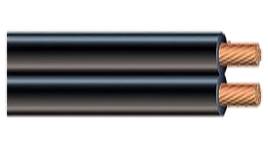
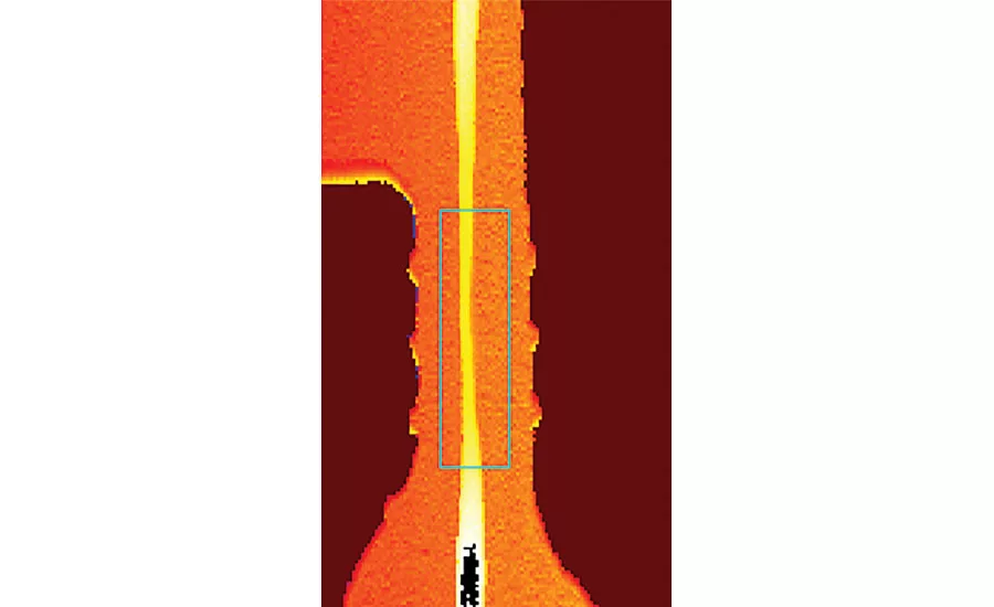
3D vision can also help address the problem of measuring defects in an object when the defects are smaller than the object geometry and when there is positional uncertainty of the part. A typical example is where cables are moved within the manufacturing process. The cables often need to be inspected for surface flaws or other defects along the jacket. In the case of electrical cabling, the wire is cylindrical and also free to move up and down by a distance greater than the size of the surface defects that need to be detected. These types of inspections can be successfully carried out through the use of 3D laser displacement sensors and special 3D algorithms which effectively remove the curvature of the object and effectively flatten out the surface of the cable so that small surface defects stand out. Such 3D algorithms also create a running average of the z-axis of the surface of the cable in order to compensate for upward and downward movement. With the large scale variations in the cable surface eliminated, the surface defects of concern can easily be identified with the use of 3D vision tools.
When adhesive is applied to hold two components together or seal a joint against the elements, the position and amount of adhesive is often critical. This is typically used in automotive components where room temperature vulcanization (RTV) silicone adhesive is applied to the cast housing and the adhesive volume and position needs to be controlled to maintain a proper seal. It’s often possible to determine the footprint of the adhesive using 2D machine vision or a human inspector but these techniques cannot accurately determine the volume of the glue and struggle when the background is the same color as the adhesive. A 3D vision system determines the height, width, volume and position of the adhesive, making it easy to determine that both the correct amount has been applied and it is in the right position to seal the part.
The food processing industry also has many applications that are difficult to automate with 2D vision systems. For example, if a bag is properly heat sealed, it should be flat and of a consistent thickness. If there are air-holes and defects inside the seal, the thickness measurement will be off. This type of defect is very difficult to detect with either 2D vision systems or human inspectors because the defects are tiny and often hidden by the seal. Two 3D sensor heads, placed opposite to one another, are able to accurately measure the thickness of the heat seal, or any object. In this application, each system measures the height of the surface of the seal. These measurements are then combined to determine the thickness of the seal, which will call out any small thickness variations that indicate the presence of contaminants. 3D vision identifies the defects during inspection and can locate where in the seal the defect is. Other applications for 3D vision in food processing include measuring the rise of dough for baked goods, the volume of food products, and defects such as missing entrée items in a frozen dinner based on volume calculations.
Conclusion
There is a growing trend in quality inspection to perform more 3D analysis of objects because it provides data and information that cannot be obtained from 2D alone. The new generation of 3D vision systems can automatically perform inspections that are not well suited to 2D machine vision and manual inspection by generating a topological representation of the part that can be used to measure 3D features such as length, width, height, tilt or volume relative to any surface. The data provided by in-line measurement is another major advantage that often enables quality managers and engineers to rapidly improve the process. V&S
Robert Tremblay is product marketing manager for Cognex Corporation.
Cognex Corporation
One Vision Drive, Natick, MA 01760-2059
1-877-COGNEX1
[email protected], www.cognex.com
Looking for a reprint of this article?
From high-res PDFs to custom plaques, order your copy today!


