The 10 Commandments for Selecting and Using Air Gaging
When followed properly, these will provide a highly successful inspection system.
The vast majority of air tooling measurements fall within the range of .111” to 8”. But that is not to say that small or larger applications cannot be solved with an air gage. Source: Mahr
As air is compressible and system pressure must stabilize prior to measurement, one way to speed the process is to never have the air tooling flow to open atmosphere. This involves using a master or part replica for when the gage is not actually measuring a part. For example, the air plug could be in the master when at rest, and when the part is placed on the master, the plug moves into the part without any drastic air pressure change. Source: Mahr
Understanding the geometry of the part is key in any dimensional check. But because of the ability of air gaging to measure some very tight tolerances, the form error can take up a significant portion of the dimensional tolerance. Source: Mahr
Air jets do not measure a ‘point’ really, but the average area of the surface the jet is covering. When finish, or roughness, of that surface is considered, the measurement point of the air jet is actually the average of the peaks and valleys the jet is exposed to. Source: Mahr
Air gaging has many advantages as an inspection method. It is quick and easy to use, and requires little skill on the part of the operator. It is highly adaptable to measuring special features for both dimensional and geometric tolerances, ranging from simple IDs and ODs to taper, flatness, and runout. With different tooling readily installed on the gage display unit, it can be highly economical. And as a noncontact form of measurement (in the sense that there are no hard contacts), air gaging is useful for measuring delicate or flexible surfaces, and surfaces easily marred with normal contacts.
Air gaging is a great choice for part inspection, but since it is virtually custom made per application, it is critical to know the commandments for selecting and using air gaging before making that purchase decision. Followed properly these “Thou shalts and Thou shalt nots” will provide a highly successful inspection system.
1. Know what you need to measure
Sounds pretty basic but this can often be a point of contention based on how the part may be specified, drawn up or manufactured. Are you tasked with measuring an inside diameter, a partial inside diameter, outside diameter, length or width? One of the great advantages of air gaging is the small jets used to sense the surface of the part. Being so small, multiple jets can be placed in close proximity and in some very small pieces of tooling to create solutions that not only measure diameters and lengths, but through signal combination can provide indications of straightness, squareness, taper, roundness, concentricity or parallelism.
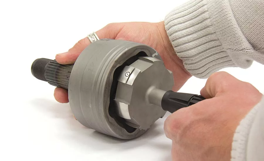
2. Know where the feature is to be measured
Because air tooling is custom designed, it can be manufactured to meet almost any dimensional application. Tooling can get the air jet down into a deep bore, or onto the shoulder of a large shaft while still in the turning center, but you have to know specifically where the check is to be made and the limitations of the air jet. Jets can be very small and versatile, but the laws of physics do control their performance. One limit is the width of the land to be measured. In order to work properly, the air jet has to be completely covered by the surface to be measured. Thus, if you need to measure a small land on an ID, it needs to be at least .100" to 0.05" wide depending on the air system used. Then again, tolerances of the position of the land and the reference surface can also influence this.
Another limitation might be the location of a jet to measure a blind hole. Since air is the lifeblood of air gaging, it needs a path to the air jet. At some point it becomes physically impossible to machine a path to the air jet in a blind tooling application. Depending on the air tooling configuration, the limit for a blind jet stands at around .045".
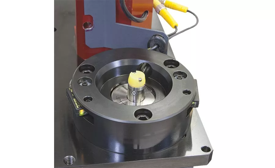
3. Know the size of the dimension to be checked
The vast majority of air tooling measurements fall within the range of .111" to 8". But that is not to say that small or larger applications cannot be solved with an air gage. On the larger side, for example, if you need to measure a very tight tolerance 16" bore on a large transmission housing, there may be no other process that will give you the same performance at the point of manufacture as a special air plug made for that application.
On the other hand, trying to manufacture an air plug for a 0.060" hole pushes the limits of manufacturing. But there may be another solution for air with these applications. Instead of making a plug to go into the hole, systems can be designed to use these small holes as restrictors and measure the hole by how air passes through it. In other words, use the hole itself as a jet. This does not provide any geometry of the diameter, but is a good indication of hole size.
4. Know the tolerance
Air gaging is a comparative, short range, high magnification measuring system. The physics of the process produces a sweet spot for range and performance. Air does not have the versatility of a micrometer, but it is faster, more accurate and easier to use. Typically, most air gaging is used for tolerances of less than ±0.001" having resolution to 10µ" or less. However, on certain applications tolerances up to ±0.005" can be provided, with some recognized limitations in performance.
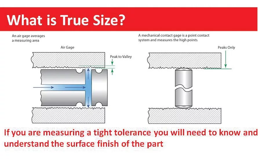
5. Know the surface finish of the part
The response of air to surface finish is a little complicated. Air jets do not measure a ‘point’ really, but the average area of the surface the jet is covering. When finish, or roughness, of that surface is considered, the measurement point of the air jet is actually the average of the peaks and valleys the jet is exposed to. This is not the same measured point you would have if a contact type probe were used. This difference is a source of real gaging error, and one that is most often apparent when two different inspection processes are used.
As a general rule, the limit for surface finish with an air gage is about 60µ" Ra, but it really depends on the part tolerance.
This source of error should also be considered when setting the plug and comparator to pneumatic zero. For most applications, there should be no more than 50µ" Ra difference between the master and the part the gage is measuring. Even this can be significant if the tolerance of the part is as little as 0.001".
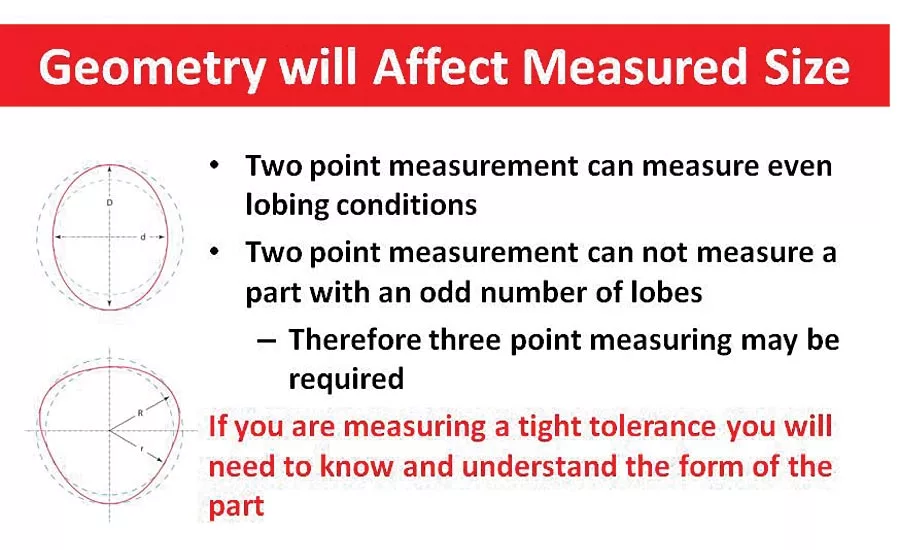
6. Know the form of the part
Understanding the geometry of the part is key in any dimensional check. But because of the ability of air gaging to measure some very tight tolerances, the form error can take up a significant portion of the dimensional tolerance.
Generally speaking, out-of-roundness is either symmetrical, involving regular or geometrically arranged lobes or points on the part’s circumference, or asymmetrical, where lobing is not regular. Most machining processes create symmetrical lobing, producing either an even or an odd number of lobes.
Where an even number of lobes is arranged geometrically on the part, each lobe is opposed by one diametrically opposite. The piece, therefore, will have major and minor diameters. Knowing this, we can gage the part using a simple two-point air plug or ring. The difference in the measurements is easily read and can even be used to provide an indication of out-of-round conditions.
Parts with an odd number of lobes pose a slightly more complicated problem. In this case, each lobe is diametrically opposed by a flat area. These parts cannot be measured with a two-point air plug system since it will read the same value as the plug is rotated through the diameter. However, by using an air tool with three jets, when the tool is rotated in the part, it would pick up the max and min diameters, providing the needed results for out-of-round or for matching with other components.
7. Do not hurry
Air gaging is based on the physics properties of air, and air is compressible. This means that once the air jet is restricted by the part, the air channels in the tooling and air hose have to fill up with air and stabilize to the backpressure created by the restriction. In applications with very long hoses this can be quite noticeable. For most bench top, manual gaging applications this delay can be easily tolerated. But for high speed automated gaging applications, even a part of a second delay may be too much and either slow the machine speed or potentially provide incomplete measurements.
There are two ways to help speed the air pressure drop recovery issue. Since most automated applications require an air-to-electronic signal conditioner, the first step is to move the convertor as close to the tooling as possible, thus reducing hose length. The second is to never have the air tooling flow to open atmosphere. This involves using a master or part replica for when the gage is not actually measuring a part. For example, the air plug could be in the master when at rest, and when the part is placed on the master, the plug moves into the part without any drastic air pressure change. This speeds measurement and also has the benefit of mastering prior to each part measurement.
8. Do not go to the mountain
We all know that air is thinner at higher altitudes than at sea level. Believe it or not, this can have an effect on the calibration performance and should be taken into consideration when ordering air systems in high altitude applications, or in sending systems to plants in locations other than your own.
9. Have a long life
Air gaging is a noncontact measuring system—at least in so far as it uses backpressure and not physical contact to measure. However, even with the cushion of air between the tooling and the surface being measured, there is still going to be some part-to-gage touching somewhere along the line, which can cause wear. For a majority of long part measurement applications this is not apt to be an issue, or is one that can be easily remedied by reorienting the tooling occasionally to move the wear points around.
Significant tool wear would most likely show up in handheld applications where a worn plug, having more body clearance, would show up as an increase in repeatability errors. In fixtures where the tooling and part are held the same way every time, and where mastering and measurement are in the same orientation, this error might not be seen. But in the case of automatic gaging where potentially millions of parts are to be measured, special material can be used to increase the life of the special air tooling.
10. Understand the application
Air gaging has the capability to provide fast, accurate dimensional measurements. And the goal is to provide the results that match the user’s needs. So consider the results that you want the users to work with. For example, with a taper application, is it important to know just the angle or is important to also know the angle and the size of the diameters at locations along the taper? When doing a match gaging application, does the user want to see the actual clearance between the parts, or just the deviation from the nominal clearance? In either case, both can be done, but these are the questions that should be reviewed and answered before creating the application.
You needn’t be a divine to appreciate the flexibility of air gaging, or to understand how it can simplify gaging tasks. Just remember that virtually all kinds of measurements—both dimensional and relational—can be performed with air, and that the more complex the task, the more air commands attention.
Looking for a reprint of this article?
From high-res PDFs to custom plaques, order your copy today!


