Reverse Engineering: Outputs
Learn more about these eight options using 3D scanning.

7. Hybrid CAD: In this example, the internal features (upper right) are critical and may need to be modified for bearings or other components, while the exterior (upper left) does not need to be changed.
The process of reverse engineering using 3D scanning can yield many outputs and there is certainly some confusion between them. I hope this brief explanation of options can help set you down the correct path for your needs.
1. Raw Point Cloud Data:
The term raw is certainly a defining feature. Nearly all 3D acquisition devices capture surface geometry in its purest form, a series of points defined by specific 3D coordinate. The position of these points relative to each other represent the surface of the geometry being acquired. Their positional accuracy is determined by the acquisition hardware being used. It is the most accurate representation of the surface, with a caveat. Raw data is as it sounds, the good and the bad. Be it structured light or laser based scanning hardware, reflections may occur resulting in false feedback to the hardware sensors. These result in residual noise scattered along with the remaining good points that were captured. With raw data also comes larger file sizes, containing all the mathematical positions of millions of points. Long range applications, including Lidar, time of flight and phase shift systems can capture millions of raw points in a matter of seconds. Also, anyone who has opened a raw point cloud knows that they are harder to visualize compared to other data sets that will soon be mentioned. Common formats are .XYZ, .ASC & .TXT.
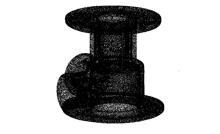
1. Raw Point Cloud Data: Anyone who has opened a raw point cloud knows that they are harder to visualize compared to other data sets that will soon be mentioned. Here’s a sample image.
2. Representative Mesh (Non-Watertight):
A mesh is a tessellated point cloud, created by connecting the raw data points with three-sided polygons. The data can be a simplified version of the raw data based on some filter criteria to remove any redundancies or noise. The filter criteria is typically specified in most post processing software. This simplified model can accurately represent the part, but has a significantly smaller file size. While at the same time, it is much easier to visualize than its raw data counterpart. Non-watertight may contain open boundaries (holes) due to line of sight issues with the scanning hardware. Open holes or gaps in the data can prevent volume calculations because the mesh does not contain a contiguous ‘skin.’ One downside to non-watertight meshes is they may not satisfy a direct input for the 3D printing process. Common formats are .STL and OBJ.
2. Representative Mesh (Non-Watertight): Non-watertight may contain open boundaries (holes) due to line of sight issues with the scanning hardware.
3. Mesh (Watertight):
Same creation parameters as the non-watertight mesh, but with all open boundaries closed. These closures can be resolved using several methods. One preferred method is fully capturing the surface data during the scanning process. That one extra scan can eliminate hours of post-production work and possible wrong assumptions. When scanning it fully is not an option, there is a variety of editing software that can close those gaps. These watertight variations of a mesh satisfies the input requirement of almost all 3D printers. These can also be used for downstream finite element analysis (FEA) and even mold flow simulations. Common formats are .STL and OBJ.
3. Mesh (Watertight): Same creation parameters as the non-watertight mesh, but with all open boundaries closed.
4. NURBS Model:
NURBS stands for ‘non-uniform rational b-splines.’ This type of model consists of a curve network applied directly to an underlying mesh controlled by allowable fit tolerances. When applied correctly this can be an extremely accurate representation of the object being scanned. The final surface ‘skin’ represents the CAD surface used for downstream applications, i.e. machining, FEA, etc. One of the most common types of uses for this process is organic materials, like the human form and sculptural work. NURBS applied to a watertight mesh will result in a solid model. One negative to these outputs can be file size. Common formats are .IGES, .ST(E)P, .X_T.
4. NURBS Model: This type of model consists of a curve network applied directly to an underlying mesh controlled by allowable fit tolerances.
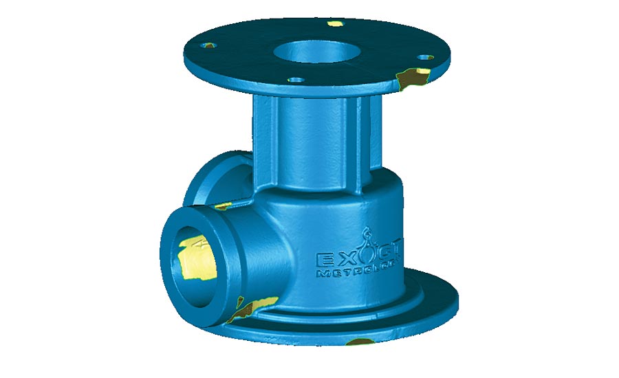
5. Clean, “As-IS” CAD:
An as-is CAD model is defined by prismatic CAD geometry constructed over a mesh file. Those features conform to the part shape regardless of traditional design rules and dimensional constraints. For example, features assumed to be in a pattern are created in their physical location. This may be critical when trying to represent the part accurately, while using CAD type features. The image seen at the right illustrates the part modeled using CAD functionality, while not conforming to what the part ‘probably’ should be. This is a critical step, especially if you are designing fixturing or mating parts that need to hold or conform accurately. The types of outputs are extremely lightweight for downstream CNC/CAM processing, but they may sacrifice some accuracy based on the nature of how the model was built. Common formats are .IGES, .ST(E)P, .X_T.
5. Clean, “As-IS” CAD: This image illustrates the part modeled using CAD functionality, while not conforming to what the part ‘probably’ should be.
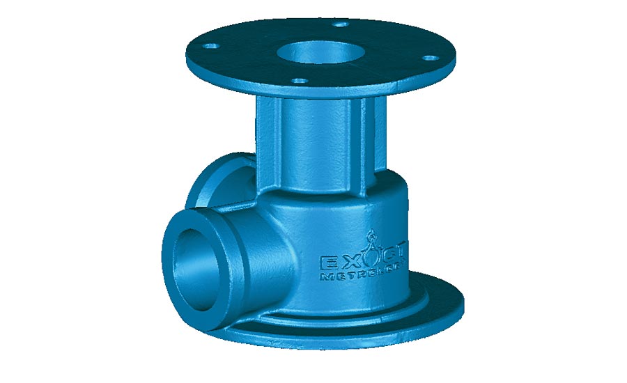
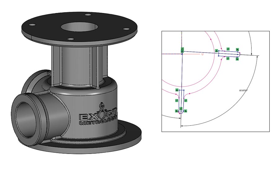
6. Clean, Design Intent CAD:
A clean, design intent model follows the same modeling path as the as-is CAD model with the exception that while features are being created, they are corrected to modeling standards, i.e. dimensions are corrected to rounded, logical values. These steps are important if the use of the data will be used, for example, for machining a new part. Overriding the actual design, with design intended allows corrections to be made. Another example would be correcting for shrink in the part, or sink marks. The rules of a NURBS model or as-is model would say that that CAD feature or CAD surface should conform to those imperfections. Design intent ignores those imperfections and corrects for where that surface should be. In the as-is example, the vertical ribs on the CAD file are at 87.98 degrees apart, the example below shows the underlying scan data, and corrects the angle to a perfect 90 degrees. Common formats are .IGES, .ST(E)P, .X_T.
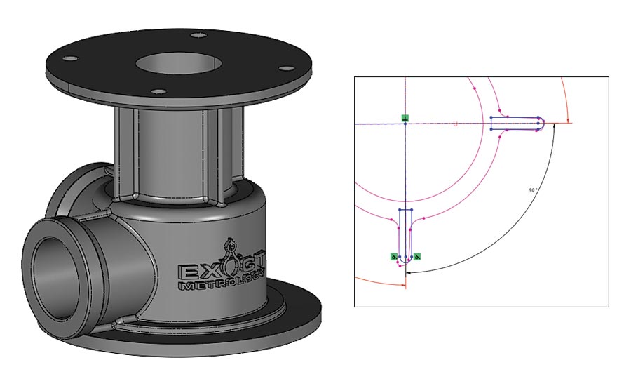
6. CLEAN, DESIGN INTENT CAD: In the As-Is example, the vertical ribs on the CAD file are at 87.98 degrees apart; the example here shows the underlying scan data, and corrects the angle to a perfect 90 degrees.
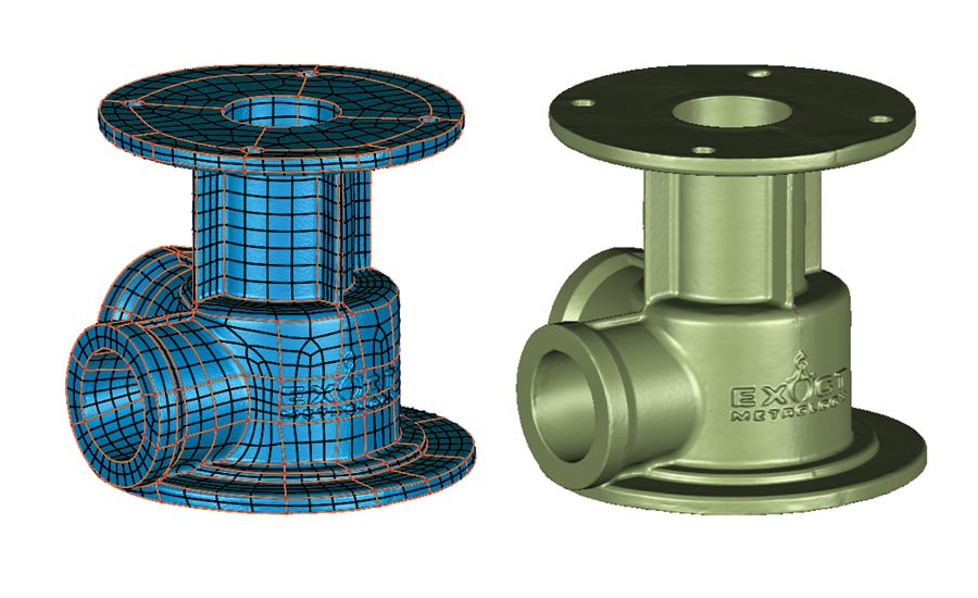
7. Hybrid CAD:
A hybrid CAD model is the combination of NURBS and design intent/as-is CAD models. The combination allows the models to conserve tolerance in critical areas (NURBS), while giving modifiable features in interface areas (design intent). In this example, the internal features (upper right) are critical and may need to be modified for bearings or other components, while the exterior (upper left) does not need to be changed. Common formats are .IGES, .ST(E)P, .X_T.
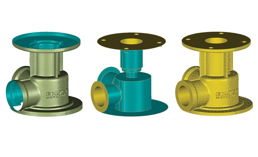
7. Hybrid CAD: In this example, the internal features (upper right) are critical and may need to be modified for bearings or other components, while the exterior (upper left) does not need to be changed.
8. Native CAD (Fully Parametric):
A native CAD model is defined as a model that shares the native properties of the host CAD software. Features can be constrained and modified using the CAD functionality. This type of model can also be defined as ground up design, i.e. modeled direct from provided print, or napkin sketch. This type of output is done by a wide variety of software with the common players being Solidworks, Creo, Catia etc. One advantage is you aren’t reliant on a heavy point cloud or mesh data set to drive the CAD features, giving you creative freedom to design as needed. This is also a con, as the previous mentioned outputs rely on the underlying mesh and can validate how well the CAD geometry fits. You have a baseline for comparison. Output formats are determined by the CAD package being utilized.
8. Native CAD (Fully Parametric): A native CAD model is defined as a model that shares the native properties of the host CAD software.
Looking for a reprint of this article?
From high-res PDFs to custom plaques, order your copy today!


