Model-Based Definition Puts GD&T Data to Work
Quality inspection used to be a disparate process isolated in a lab. Today it is much more integrated with the production floor through in-process inspection and open CAD-based measurement software.
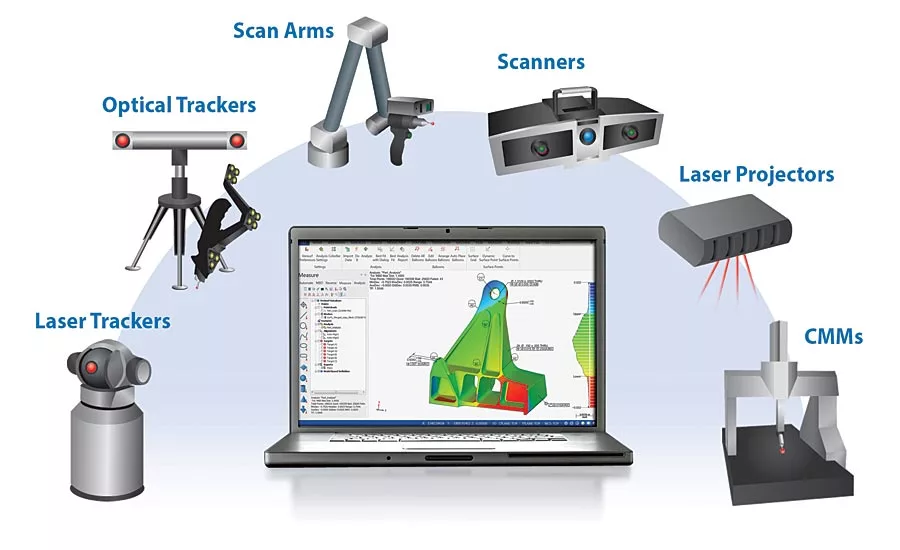
It is important the model-based inspection software serve as a common platform and communicate openly with all CAD software and all metrology devices.
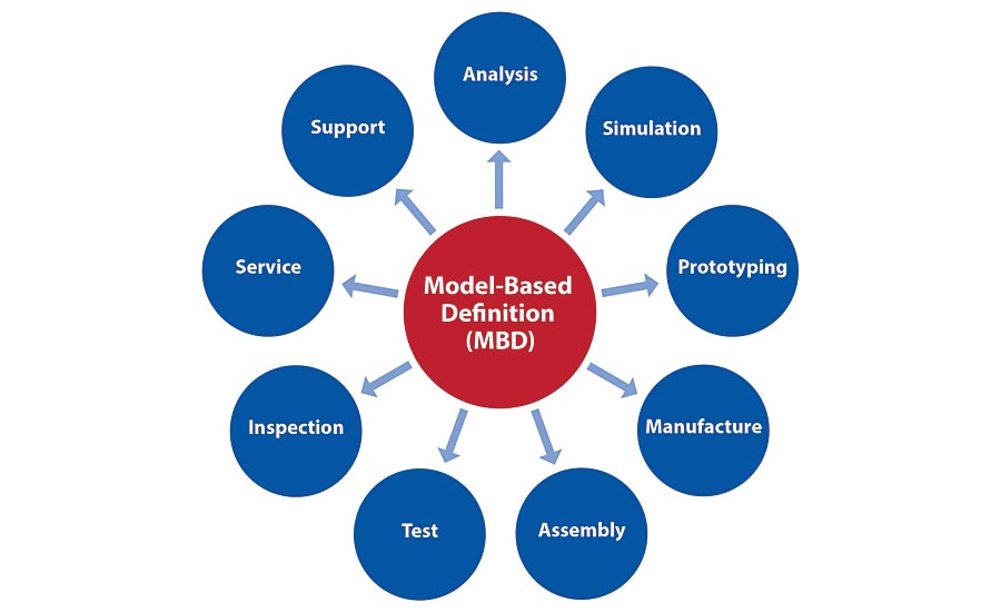
You hear a lot about Geometric Dimensioning & Tolerancing (GD&T) today, but less about its practical deployment and utilization in the manufacturing and inspection process. To better understand and appreciate the importance of GD&T data one must embrace the idea of Model-Based Definition (MBD), which gives the annotated data relevance in the design, build and quality-verification processes.
MBD came out of the verifiable, close tolerance world of aerospace manufacturing, which challenged us and other metrology companies to provide a practical means to inspect and report part quality across an ever-increasing supply chain. Before the globalization of aircraft manufacturing, OEMs made most of the components they used, but as multi-tier supply chains emerged so did the need to reduce time-to-market, improve quality and effectively communicate and manage design intent of every part produced.
Boeing was one of the early adopters of MBD, which is a requirement for doing business with the company as outlined in Document D6-51991, Quality Assurance Standard for Digital Product Definition at Boeing Suppliers. A Boeing dataset is provided containing the exact solid, its associated 3D geometry and 3D annotation of the product’s dimensions and tolerances (and may include parts/notes list) to specify a complete product definition. Model Based Definition provides a single source of product definition, which reduces conflict between CAD and paper drawings. As a result, the Boeing dataset neither includes nor requires a conventional 2D drawing. MBD first proved its value in the aerospace industry, but is quickly becoming a requirement throughout many manufacturing segments.
Under the MBD concept, the 3D CAD model should contain everything needed to confirm design intent, to manufacture and to verify quality; this includes supporting GD&T annotations. The lines between various acronyms and digital concepts are easily blurred and often misused; just remember, in an MBD environment the 3D CAD model is the authority. MBD is a scalable strategy that can support the design-build process of machining and validating parts, or be expanded to include the complete Product Lifecycle Management (PLM) process. The key is to not be overwhelmed or intimidated by MBD, but rather to get onboard with the concept at a level that makes sense for your company; whether you are an OEM, tiered supplier or job shop, MBD saves time, improves quality and reduces scrap and rework.
MBD opens the door to:
- Model-Based Engineering
- Digital Product Definition (DPD)
- Model-Based Manufacturing
- Product Manufacturing
- Information (PMI)
- Model-Based Inspection and reporting
- Product Lifecycle Management (PLM)
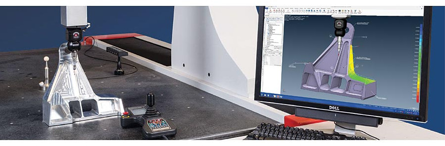
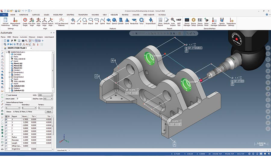
Here software is being used to perform model-based inspection using a programmable CMM. The software provides real-time deviation feedback between the nominal CAD model and the finished part, as illustrated by the color mapping.
The Role of GD&T in MBD
There is a common misconception that MBD is synonymous with GD&T. While GD&T is a necessary component of MBD, the concept of true Model-Based Definition goes much further in terms of helping to manage downstream data and processes. GD&T is a universal symbolic tolerancing language. Last updated in 2009, GD&T has been rigorously studied, and applied by thousands of manufacturers around the world. It is essential for communicating manufacturing tolerance—the information in a model that specifies the necessary form, fit, function and interchangeability. There are two GD&T data-definition formats; both are labeled “3D annotation,” but one format is purely for display, while the other provides associativity with the CAD model.
The distinction is that in the display format, tolerancing is assigned to the model in the form of text and symbols. In other words, humans must interpret the GD&T information, without opening the door to potential errors. The display or presentation format is similar to typing a math equation in Microsoft Word; it conveys information, but the computer cannot use it in calculations. In conversation, we call this approach “decorating the model.” The alternative format, Associative GD&T, links callouts for datums and tolerances to features in the model in a way that can be conveyed to the user and the application software to know what surfaces the GD&T callouts are assigned to. Since the design process typically begins on a CAD platform, it is essential that downstream applications, such as inspection software, can open, modify and provide feedback to the CAD model, including GD&T annotations. This adds value to the CAD authority by providing critical MBD data while maintaining a digital thread.
GD&T is defined in ASME Y14.5 and ISO 16792 3D; GD&T symbols include those for form, profile, orientation, location, and runout. Although there are many GD&T symbols, most CAD models can be annotated effectively using only position, profile, and flatness callouts. For example, many parts today are toleranced with a global profile applied to all surfaces in the model. Key characteristics of specific features are annotated using additional callouts.

Position: Controls the location and orientation of a feature in relation to its datum reference frame.
Profile of a Surface: Controls size and form of a feature. In addition, it controls the location and orientation when a datum reference frame is used.
Flatness: Controls the flatness of a surface in relation to its own perfect form.
Model-Based Inspection
GD&T and model-based inspection is a great place to start when moving towards MBD. It moves the CAD model from design to a manufacturing orientation. It opens the door to many advantages where software can automate and validate steps in the simulation, manufacturing and inspection processes.
MBD is a scalable strategy that can support the design-build process of machining and validating parts, or be expanded to include the complete Product Lifecycle Management (PLM) process.
GD&T defines quality requirements, and inspection then confirms these requirements are being met. For model-based inspection to occur there must be GD&T representation and the inspection-software must be able to import the data from the native CAD software, including both presentation and intelligent GD&T annotations. When intelligent GD&T data is not available, users must be able to add it to the CAD model in the inspection software.
Open Inspection and Measurement Platform
Many software programs and hardware measuring device manufacturers want to lock the customer in to their platform. Contrary to this approach, it is important that the model-based inspection software serve as a common platform and communicate openly with all CAD software and all metrology devices, across the manufacturing enterprise. This includes portable and fixed measuring devices as well as new and legacy equipment. By incorporating an open CAD-based metrology platform across your manufacturing enterprise, you have the flexibility to choose the right measuring device for each job, while economizing on training, data management and support.
Closing the Loop on Digital Workflow
Quality inspection and reporting used to be a disparate process isolated in a quality lab. Today it is much more integrated with the production floor through in-process inspection and open CAD-based measurement software, developed to support and run all types and brands of new and legacy measuring devices. Model-based inspection truly closes the loop; it feeds back to the CAD data authority with little delay, making inspection results more valuable and easier to attain. It eliminates interpretation and ambiguity concerning the design intent and functional demands. Standardizing on one inspection software across the manufacturing enterprise will provide consistency of operation, quality reporting, data management, and reduced training and support costs.
During inspection, software presents a virtual view of the intelligent 3D CAD model and measurement device being used. Within the software, users can add or modify GD&T datums to support inspection and quality reporting.
Selecting Model-Based Definition Inspection Software
Be sure the enterprise inspection software you select is open and offers the necessary level of interoperability to support your current and future manufacturing inspection requirements. Consider these questions:
- Is the inspection software model-based on a CAD platform, including 3D modeling?
- Does it import and export all CAD files and models seamlessly?
- Will it import and allow annotation of GD&T data?
- Does it accept measurement data from all digital measuring devices?
- Is the software capable of controlling all popular digital measuring devices?
- Does the software support new and legacy measuring devices regardless of age, controller type or proprietary software?
- Does it have the flexibility and embedded tools to handle the range of inspection data, from manual contact probing to noncontact point clouds?
Looking for a reprint of this article?
From high-res PDFs to custom plaques, order your copy today!


