Form Measurement: Back to Basics
Understanding common problems in the measurement of form.
Historically, the standard default value for measurements of out-of-roundness was thought of as 50 UPR. While this filter may be appropriate for many applications, it is not the right fit for all. Recent ISO standards suggest that a better approach is to consider a filter based on the diameter of the object being measured.
Form is a relatively easy thing to measure in many senses. In the simplest manner, form measurement involves a probe or stylus being moved along an ideal circular or linear path to gather data on the probe movements relative to that ideal geometry. The analysis is usually pretty straightforward; the measured data points are filtered and mathematical operations are performed to ascertain the results.
It is one of the most fundamental measurements performed in support of many manufacturing processes, but it is still a measurement where some elements of it are often done incorrectly. In this article, we’ll review the common errors that we continue to see in the measurement of form and revisit the basics in order to address them, enabling readers to achieve more accurate measurements.
Using Incorrect Filters
Realistically, form measurement is the process of measuring variations in shape. Historically, it was performed in climate-controlled labs by highly trained specialists, but nowadays, it is often performed directly on the shop floor by operators charged with a wide variety of tasks.
Whether measuring for form or roughness, the process is essentially the same. When any surface is measured, there are typically many sample points used to represent the entire surface. Those points are then filtered to obtain only the desired data. For example, when looking for surface roughness, the short wavelength data (the “small stuff”) is kept for analysis, while the data on form is discarded because that information isn’t needed. Alternatively, when measuring form, the short wavelength data is filtered out so the long wavelength data representing the shape can be measured. This is the first place where many people begin to go wrong; the nuances of filtering are not readily understood so they pick the filters incorrectly.
The filters for form measurement are confusing for many practitioners of these measurements. For example, when discussing surface roughness measurement, the conversation is about filter settings in terms of millimeters or inches. If the filter is set to 0.8 mm, then it is generally understood that variations on the surface shorter than 0.8 mm are surface roughness and elements longer than 0.8 mm are considered form errors on the surface.
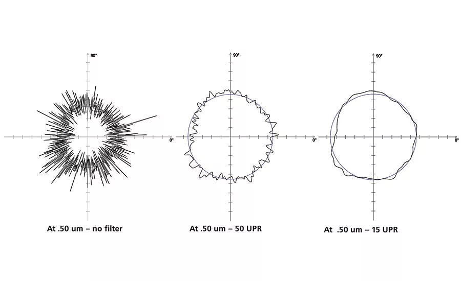
Unfortunately, form filters for roundness measurements are specified in terms of an angle rather than a length or distance. Making matters even more confusing, the specifications are not directly given as an angle in degrees, but in something called undulations per revolution or UPR. The typical value used as a default by many is 50 UPR. This means that 1/50th of a circle is the length of the filter, or 7.2 degrees.
However, the arc length equal to 7.2 degrees on the surface of a round object changes with the diameter of the object. The simple formula for circumference of a cylinder is Pi (3.14) times the diameter. A cylinder that is 4 mm in diameter would have a circumference of 12.57 mm, and therefore, 7.2 degrees would carve out an arc length that is 0.25 mm long on the surface. However, if I am going to measure a cylinder that is 20 mm in diameter, that would have a circumference that is 62.83 mm and 7.2 degrees would correspond to an arc length that is 1.26 mm. So if the same 50 UPR filter setting is kept on the measuring instrument, one will be considering variations on the surface that are 5 times larger in the case of the 20 mm diameter part to be the divider between what is form and what is surface roughness.
Historically, the standard default value for measurements of out-of-roundness was thought of as 50 UPR as previously discussed. When a 50 UPR filter is used, undulations that occur at frequencies above 50 UPR are automatically filtered out. While this filter may be appropriate for many applications, it is not the right fit for all. For this reason, recent ISO standards suggest that a better approach is to consider a filter based on the diameter of the object being measured. If an operator needs to measure smaller diameters (under 8 mm) on objects such as master pins, small fuel injector needles, or hydraulic valve components, etc., the ISO standard recommends considering the use of a 15 UPR filter rather than the default 50 UPR. In everyday practice it seems that this idea is not taken into consideration and many operators simply measure everything with the 50 UPR setting. Changing this is as simple as clicking a button in the software of most measuring instruments—however many don’t understand the meaning of UPR and therefore don’t change it.
Sometimes the opposite problem also occurs. Without understanding that the UPR setting can dramatically change what is filtered out of the data or kept in the analysis, operators might be tempted to change it because setting it to a different value changes the results and can lead to a “better looking” result but isn’t really correct for the size of the part being measured. The bottom line is the filter should be set correctly for the object to be measured.
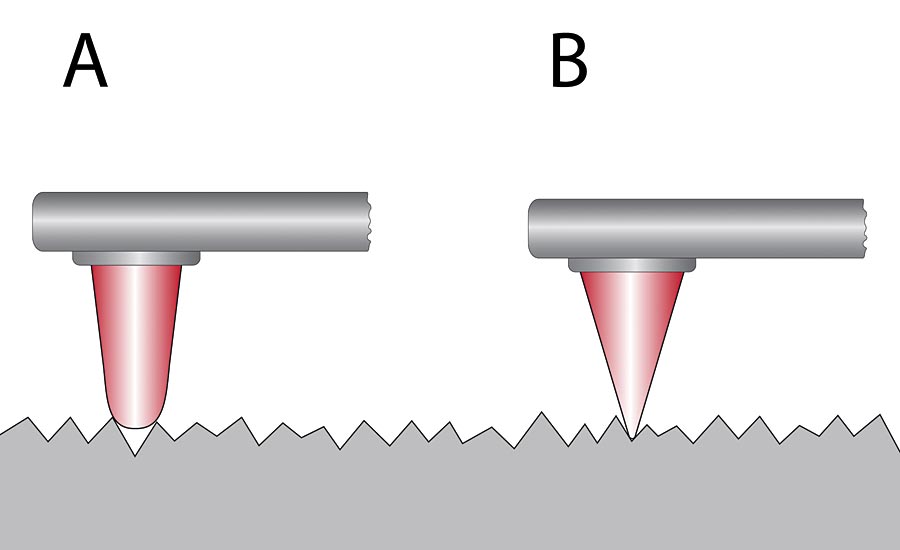
If you are touching surface with a probe that has a ball tip on it that is too large, it is not going to follow along the surface properly and accurately move in and out of the peaks and valleys.
Incorrect Stylus Tip Size
It is also common that users will rely on a single stylus tip for measuring all parts, regardless of the size of the part being measured. In reality, the stylus tip itself represents a mechanical filter that should be selected according to the part size and the maximum number of undulations per revolution that can be measured.
To revisit the smaller diameter measurement example, if touching surface with a probe that has a ball tip on it that is too large, it is not going to follow along the surface properly and accurately move in and out of the peaks and valleys. Using tip sizes on a probe that approach the size of the part’s own diameter makes it very difficult to get a good evaluation of the surface. In this case, using this tip causes its own type of filtering before any filtering has been done mathematically.
Because of this, recent ISO standards also give the user guidelines to help in selecting the correct probe based on the UPR settings. The recommendation is given as a d:r ratio where “d” is the diameter of the part being measured and “r” is the radius of the probe tip. To revisit the earlier example of the 4 mm diameter cylinder being measured using a 15 UPR filter setting, the recommendation in the ISO standard for 15 UPR would be a d:r ratio of 5. That means that the stylus tip radius should not be larger than 0.8 mm (or 1.6 mm diameter). However, for the 20 mm diameter cylinder, it would be measured using a 50 UPR filter setting and the recommendation for that is a d:r ratio of 15. In that case, the stylus tip radius should not be larger than 1.3 mm. In both of these cases, a tip radius that is smaller than these values is okay but anything larger than the recommended value could begin to filter the data unintentionally during the measurement.
Conclusion
Even though form measurement is one of the basic tasks used to support numerous manufacturing processes, many operators commonly perform some aspect of it incorrectly without even realizing it, affecting both measurement quality and the overall quality of the finished product. Ensuring that basic steps such as using the correct filters for the situation and getting the right data for what you need, as well as using the best tools such as properly sized stylus tips for the application, can go a long way to increasing the quality of measurement data and ultimately the quality of the parts. Q
Patrick Nugent is vice president, product management at Mahr Inc. For more information, call (401) 784-3100, email [email protected] or visit www.mahr.com.
Looking for a reprint of this article?
From high-res PDFs to custom plaques, order your copy today!


