Surface Crack Fracture Mechanics Testing
There are many different types of crack types and geometries that can occur in structures, whether caused by manufacturing defects, poor process control, or during the intended service.

Fracture mechanics testing including fracture toughness and fatigue crack growth testing is important to the safe design and operation of structures. In this paradigm, the fracture toughness of a material describes the ability of the material to withstand a static load before failure. The durability of the material is measured by the rate of fatigue crack growth in which cyclic loading grows a crack over time.
There are many different types of crack types and geometries that can occur in structures, whether caused by manufacturing defects, poor process control, or naturally during the intended service. The most commonly evaluated crack is what is considered a through-flaw in which the flaw penetrates all the way through the thickness of the part. Methods for evaluating a through-flaw are readily available and well-known.
Another class of cracks are so-called surface cracks where the crack does not penetrate the full thickness of the part. The need to evaluate surface cracks is most prevalent in the aerospace industry in which lightweight structures are paramount, and the critical flaw sizes at which fracture occurs are relatively small. Typical scenarios that involve surface cracks include but are not limited to a crack growing in an engine turbine blade at elevated temperatures, or a crack growing from a structural rivet hole.
When performing a fracture mechanics test, it is advantageous, if not required depending on the test type, to measure the crack size as a function of applied cycle count or applied load. For example, measuring the crack size is required by ASTM Standard E1820-17a which is a common test method for determining nonlinear fracture toughness. Unfortunately, surface crack tests are uniquely challenging because there is no convenient way to monitor crack size in a surface flaw for cracks with an evolving (changing) shape.
Most surface cracks have an evolving aspect ratio, which relates the maximum crack depth to the observed crack length as measured on the surface. This is the typical situation, since the driving force for crack growth, the stress-intensity-factor, K, is a function of the part geometry as well as the applied load. In fracture mechanics, K is more relevant to the behavior of the crack under load than stress alone because K delivers information on stress and crack size together in a single parameter. Another mitigating factor is that parts may be small enough relative to the crack such that the crack does not behave as if it is located in a sample of infinite size. In an infinite sample, the surface crack would grow to a semi-circular shape and stay as such, but this is not true for surface cracks in a finite sample. Stated in another way, the boundary conditions of the loading affect the surface crack development and evolution.
In order to overcome these limitations, an interactive tool was published by NASA that provides the capability to nondestructively monitor the instantaneous crack size of an arbitrarily shaped semi-elliptical surface crack growing under tension or bending in a finite test sample. This software is referred to as Surface Crack Potential Difference (SCPD) and was awarded the NASA Marshall Space Flight Center Software of the Year Award in 2010. (This software is available to federal employees and contractors to the federal government working on projects where this would be applicable. It can be located at https://software.nasa.gov/software/MFS-32848-1.)
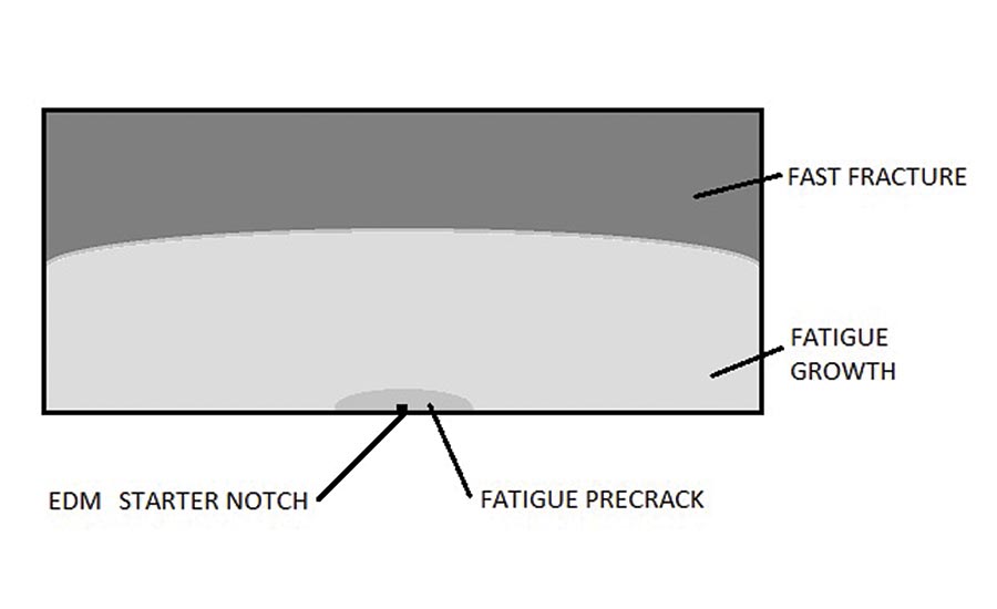
Schematic of a surface crack cross section showing the initial machined notch, precrack, and test region. The precrack is typically a target size for a given test.
The tool couples a model for predicting the evolution of the crack with a model for real-time monitoring of the crack size. The engineering model for crack evolution is known as Newman-Raju. The experimental crack monitoring method uses one of the two most common methods, known as potential difference (PD). PD operates in a simple way using elementary physics. A constant current electrical power supply provides current flow through the metallic sample. Probes attached to the sample on either side of the crack monitor the potential difference, or voltage, across the crack. As the crack grows the resistance of the current path increases because the remaining area for the current to pass around the crack has been reduced due to the increased crack size. Because the current is maintained constant, the voltage increases. This increase in voltage is measured as the independent variable and is used to correlate with crack size. Mathematical equations for the voltage between probes on the specimen surface have been determined for many through-flaw geometries. The most well-known is Johnson’s Equation, applicable to so-called middle-tension and also to compact-tension samples under certain scenarios. Ultimately, a mathematical relationship, termed the calibration, must be developed to relate the empirical change in the measured potential difference (PD) to crack growth. The calibration is independent of material and is unique to the crack geometry and PD configuration.
The SCPD software facilitates the accurate and repeatable production of desired surface crack sizes for subsequent fatigue or fracture testing. This permits any desired crack growth driving force to be delivered to the sample containing the evolving surface crack via automated computer control. Because this tool allows for the direct measurement of surface crack growth rates, it eliminates the assumption that a surface crack size and shape will grow at an equal rate as does a through-crack. These capabilities produce higher-integrity material data which will lead to more accurate surface crack damage tolerance assessments.
The input to the model is the specimen size, initial size and aspect ratio of the surface flaw, the mode of loading, the fatigue crack growth parameters, and the configuration of the potential difference instrumentation. The output of the program is the expected crack evolution, and the resultant crack depth versus measurement signal calibration for the given model.
To summarize the process, an initial surface flaw is assumed to be loaded in either tension or bending. The Newman-Raju stress-intensity factor equations for the surface crack are updated with finite specimen width correction factors to determine the stress-intensity along the crack boundary. The change of shape of the surface crack is predicted from the calculated stress-intensity values along the crack front. The model performs numerical calculations assuming that crack growth will be driven in the depth by some small increment. From the evolution of crack shape, the voltage vs. crack size relationship can be determined. This methodology enables improved damage tolerance analyses resulting in greater overall safety for fracture critical structures containing surface flaws. Q
Looking for a reprint of this article?
From high-res PDFs to custom plaques, order your copy today!


