Calibrating Surface Gages for Success
The measurement of surface finish has come a long way in the past 70 years.
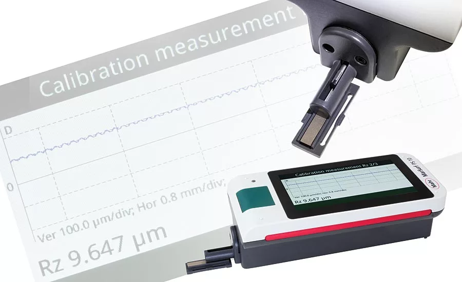
The reference standard is the tool that checks the performance of the surface finish instrument to a traceable standard. Systems with a built-in standard provide the possibility of much more frequent verification of the measuring process.
Surfaces are designed into products to reduce friction, “store” lubricants, provide a high luster finish or be the proper texture to hold paint (but not show the actual surface of the paint). The measurement of surface finish has come a long way in the past 70 years. It has advanced from fingernail scratch pads to microprocessor or PC-based systems with inductive probes. And today, there is an explosion of optical sensors to evaluate part surfaces with noncontact methods to levels unheard of in the past.
ISO processes require the documentation of surface finish quality and traceability of surface finish measuring instruments. The vast majority of surface texture checking systems are still the contact type with a very fine stylus being dragged over a part. That is why there is an increasing importance of calibration and certification for surface finish gages.
Surface Finish Gage Inspection & Calibration
There are two basic varieties of contact surface finish gages: skid-type, or averaging systems, and skidless, or profiling systems. Skidded gages have a hinged probe assembly, with the probe riding next to a relatively broad skid that also contacts the workpiece. The skid tends to filter out waviness, so the probe measures only short-wavelength variations. A skidded gage has a digital readout to display the measurement as a single numerical value. By having this numeric value of the results from the measuring system, it now becomes possible to record or document the results, and by having certified reference standards, these results can be traceable to international standards.
For the purposes of this article, we will take a look at the calibration process and documentation of the results for the most common skidded probe surface finish measuring system. However, prior to actually doing the calibration process, good practice always calls for the general inspection of the system. Often this involves a quick once over, ensuring that everything works, the system is complete and not damaged, etc.
Once you are ready to check the performance and calibrate a surface finish gage, the next step is to look at the actual contact of the surface finish probe. Proper care of contact points is one of the basic considerations of any gaging. Whether you’re using a simple indicator gage or a sophisticated surface finish instrument, much depends upon the condition of the sensitive contact point, which is the interface between the gage and the workpiece.
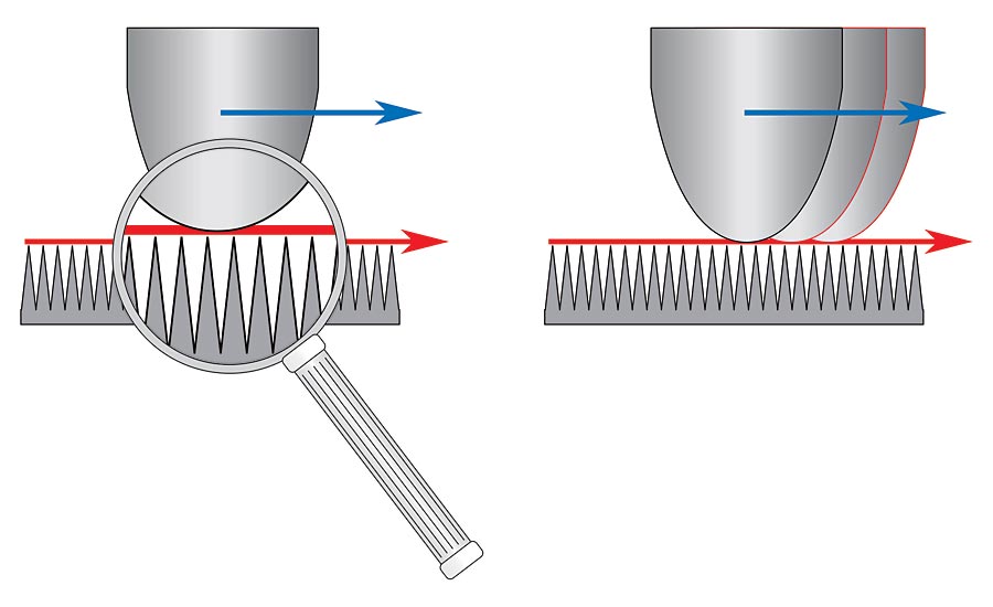
Dial indicator contacts are easy to inspect. They’re large enough to get your fingers around, and you can check them visually for wear, damage or contamination. However, the tiny contacts on surface finish gages are quite another matter. Compared to blunt dial indicator contacts, a surface finish gage has a fine “stylus” point, enabling it to follow the texture of the surface, but being of a form and dimension so as to avoid scratching the part. Gaging force from a dial indicator is typically 120 grams/1.2 N; in contrast, force from a surface finish gage is light, usually between 100 mg and 1,500 mg (1 mN to 15 mN). Since the stylus is “dragged” across the surface of the workpiece, it is just as subject to wear and damage as a dial indicator contact.
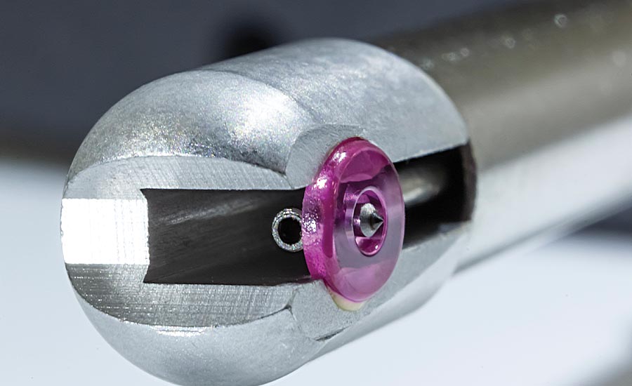
Magnified view of a roughness probe showing the skid and measuring stylus.
Surface finish contacts are made of diamond, and are conical in form, having a 60° or 90° included angle and a spherical vertex with a radius of 0.0004”, 0.0002”, or 80 microinches (10 micrometers, 5 micrometers or 2 micrometers). Criteria for choosing between these options are outlined in ASME B46.1 - 1995 paragraph 4.4.5.1. Even with its small radius, a stylus in perfect condition may be too broad to reach the bottom of the small “valleys” on the part surface. This inherent “error” is accounted for by calibration, however.
Wear or damage to the stylus will affect measurements. An evenly worn contact will typically under-report the distance between surface peaks and valleys. A broken stylus may under-report surface variation, or may over-report it, depending on the nature of the break and the part surface. On occasion, the break may be so sharp that the stylus could scratch the part: a pretty clear indication that the stylus needs replacement.
Paragraph 11.7.2 of the ASME B46.1 standard describes several more practical methods by which stylus condition may be checked. Because the stylus radius is too small to see with the naked eye, a handheld magnifier or microscope is required for visual inspection. At this point, it may be necessary to assess the stylus’ condition numerically using reference specimens. Once we get to this point, we then start to move from the visual inspection to the actual calibration process for the system, which is predicated on using certified roughness standards.
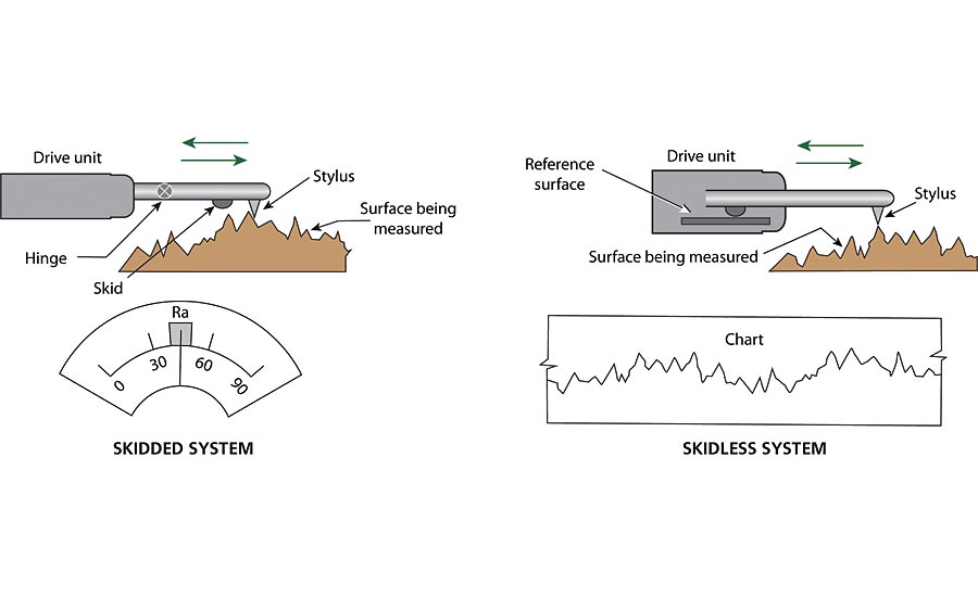
There are two basic varieties of contact surface finish gages: skid-type, or averaging systems, and skidless, or profiling systems.
The most common roughness standard is the triangular style, with rounded peaks and valleys. From the ASME B46.1-2002 standard these specimens are typically referred to as “C3 Style” grooves and come in various grades of roughness. Examples include Ra values of 0.5, 0.9, 2.5, 3.0 or 3.2µm.
It is important to make sure the system you are using has the same diamond tip radius that was used to calibrate the specimen. Since smaller or larger radius tips will fall into the peaks and valleys differently, the results from these probes will vary. You can always ask the calibration lab that certifies your specimen to use the same diamond radius you are using.
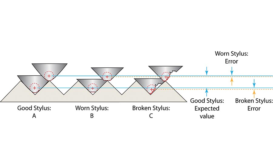
Even with its small radius, a stylus in perfect condition may be too broad to reach the bottom of the small “valleys” on the part surface, as shown in “A” in the diagram. An evenly worn contact will typically under-report the distance between surface peaks and valleys, as shown in “B.” A broken stylus may under-report surface variation, or may over-report it, as shown in “C,” depending on the nature of the break and the part surface
Conventional wisdom for the calibration process says to use a specimen that is close to the values required for your process. For example, if measuring very fine surfaces, you should use a fine calibration patch. However, this may not be the best idea. As with any gaging amplifier (which is what a surface finish instrument really is), it is best to calibrate using as much range as possible. The benefit of this is that you are exercising the probe and amplifier over their full range to ensure proper operation anywhere within the calibration range. Typically, the gage is calibrated to a certified specimen rated typically at 125 microinches (3.2 micrometers). The 125 patch provides a good sample range for the probe, and since it can be certified, the documentation and traceability required by ISO standards can be complied with.
This calibration process is fairly simple. Just make a measurement of the surface reference specimen with the instrument using the Ra parameter and see what you get. Each reference specimen comes with a certificate of what the measured Ra value is. After the test, compare the results. It should be within the percentage of error as specified by your instrument manufacturer. If not, adjust the system using the manufacturer’s process and then re-measure the reference specimen. If the results still are not accurate, there may be an issue with the unit or the probe. This two-step process provides a double check: one of the system and one of the probe.
For measurement accuracy, the ideal situation is to have the skid on the measurement probe sit atop the peaks on the surface of the part. This will ensure that no mechanical filtering of the measurement results occurs.
Once there is a successful full range calibration, it is wise to verify the total performance of the system, especially the probe with a fine calibration patch. This is important for two reasons. First, it will verify that your instrument is producing the correct results after the calibration. Second, if the result is not right, it probably is not the calibration but rather that the diamond radius tip is starting to wear. This test is the other part of the physical inspection of the probe contact. As mentioned above, it provides a numerical value test of the probe contact. As the diamond wears or becomes chipped, it will either span (ride the peaks) or go further into the valleys and give improper results. Repeat the same process with a patch certified for a typical value of 16uin/3,2um. This final test shows that the system is within its calibration limits or, if not, may point to a worn stylus.
Should damage or wear be discovered, there is only one option available: replacement. Some gages feature easy-on/easy-off contact mounting, while others require a more involved procedure. Users should be aware of the variety of contact shapes available from gage suppliers. These may include extra-long lengths, smaller diameters or special shapes that provide access to features that are otherwise hard to reach. But no matter what contact shape is used, it should be inspected regularly to ensure accurate surface finish measurements.
It is good practice to do a calibration and stylus check reading just after a new gage is received rather than waiting until after the system is put in use and due for an annual calibration. This establishes a benchmark reading when the stylus is in a new, unused condition. This initial reading becomes a useful reference for future stylus inspection.
Following these steps will provide you with a documented and certified surface measuring system that is ready to be put back on the shop floor and confidently measure parts. But as with any process, there can be exceptions. In the world of surface finish measurement with skidded systems, there can be other considerations to think about.
Probes with Special Calibration Requirements
As we have illustrated, most simple roughness measurements are made using a skidded probe. There are many different types of skidded probes available, and the characteristics of the part will typically determine what probe may be the best for the application. For example, there are probes designed to measure surface finish at the bottom of a groove or along a razor’s edge. The length of the surface that is to be measured can also dictate the style of probe to be used. With most of these types of probes, the typical testing and calibration process mentioned above can be used.
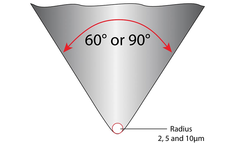
Cross section of the fine diamond point on a typical measuring stylus showing examples of various radius points.
The majority of skidded probes are longitudinal skid type probes. Longitudinal skid probes are defined as having their skid running in line with (coincident to) the length of the measurement probe. The skid surface is directly in front of or behind the measurement stylus and comes in contact with the surface to be measured. Depending on the manufacturer, the length of the skid surface before or behind the probe can vary but is typically around 0.120” (3mm). This means that the surface to be measured has to have a minimum length in order to support the skid. If the skid is unsupported during measurement, the results will be erroneous.
However, for certain applications where the surface of a radiused probe is required, a lateral skidded probe may be used. Lateral (transverse) skid type probes are designed so that the skid runs across or transverse to the length of the measurement probe. The skid surface is to the left or right of the probe. These types of probes are often a good alternative to longitudinal type probes, since the skid length is short and can be used where the measurement land areas are short in length or the area to be measured is close to a shoulder.
In the case of lateral type skidded probes, special concern of the calibration process is required. Due to the short skid length, the radius of the skid surface is also small. Again, each manufacturer has their own probe design, but this type of probe typically has a skid radius of 0.012” (0.3mm), which can cause problems in certain applications. When measuring a surface with a short skid radius in the transverse direction, it is important to consider “peak spacing” (Sm) along with the roughness Ra value, as it is not uncommon that a rough surface will have larger peak spacing. This will help ensure that the short radius skid does not “fall in between” the actual peaks which would result in mechanical filtering.
For measurement accuracy, the ideal situation is to have the skid on the measurement probe sit atop the peaks on the surface of the part (or in our case, the reference specimen). With the skid sitting atop the peaks, the stylus will travel the full dimension from the top of the peak to the lowest valley. This will ensure that no mechanical filtering of the measurement results occurs.
Thus, the same is important when it is time to calibrate the system. In this case, the lateral probe is apt to not read properly with the fuller range specimen such as the 125 patch we used previously. The peak spacing is too wide for the probe tip and reduced values are apt to be seen. In this case we have to break our previous rules and only use a reference standard of a smaller value—something along the probe check specimen used above—a specimen certified for 20u” or so. Using the proper specimen, we would know the probe is truly “seeing” the peaks and valleys and we can calibrate the system properly.
Summary
The calibration process of the typical skidded surface gage is a fairly simple process. It is not much different than certifying a dial indicator, micrometer or bore gage. Once you have a certified reference specimen that is up to date you have the means to monitor and check performance and establish the documentation needed for your ISO requirements.
Looking for a reprint of this article?
From high-res PDFs to custom plaques, order your copy today!


