Lens Selection Guide, Part 2
Understand the differences between the most common types of lenses used in machine vision.
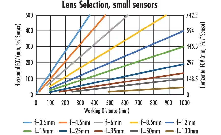
Figure 1: Lenses of different focal lengths and their fields of view on 1/3” and 1/1.8” sensors
Due to the vast number of imaging lenses that are available on the market, actually choosing a lens for a given application can be a daunting task. Part one of this article covered the most common types of lenses used for machine vision. Part two will cover how to actually go about selecting a lens once it is known what type of lens is needed. Generally, the working distance and field of view are required to be known before the proper selection of a lens can take place. Following that, the smallest feature size that needs to be resolved on the object needs to be known; this can be referred to as the object space resolution.
How to Choose a Fixed Focal Length Lens
For the purposes of this discussion, fixed focal length lenses, zoom lenses, and macro lenses can be assumed to operate on the same principles, and can be chosen in the same fashion. This assumes that zoom lenses are being specified at individual focal lengths, and that their zoom functionality has been locked down.
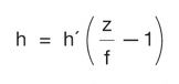
All variable magnification lenses come to focus based upon Equation 1,
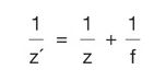
where z’ is the image distance (which can be thought of as the distance between the image plane and the last element), z is the object distance (or the distance between the object being focused on and the front lens element), and f is the focal length of the lens. This is an approximate equation that assumes that the lens has no thickness; it is included here to show the relationship between image and object distances. For a given focal length, as the object distance (working distance) increases, the image distance will decrease.
For a single lens element, such as a plano-convex or bi-convex lens, this equation can be quite useful to determine which focal length is proper given an object and image distance. However, in a machine vision system that utilizes lenses with many elements, it falls short in several ways: it does not describe what the field of view will be, and since it is impossible to measure the image distance in a machine vision lens (as it is buried into the camera and lens housing) it becomes impossible to solve for focal length.
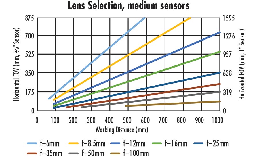
Figure 2: Lenses of different focal lengths and their fields of view on 2/3” and 1” sensors
Using the equation for magnification, Equation 2,
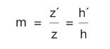
where h’ and h are the size of the image plane (most often a sensor size) and field of view, respectively, Equation 1 can be rearranged into a much more useful form, shown in Equation 3.
Equation 3 provides a quick and easy way to solve for which focal length lens is required to solve an application, given fundamental parameters such as field of view and sensor size. For the majority of applications the “-1” term can be dropped from Equation 3, as generally z⁄f»1.
Figures 1 and 2 show Equation 3 plotted for several lenses with different focal lengths, on different sensors (corresponding to separate y-axes).
These plots can be quite useful in determining the proper focal length for a machine vision lens if a camera has already been chosen: simply follow along the x-axis to the required working distance, and, using the corresponding y-axis (depending on the sensor that is being used), find where the points meet on the coordinate plane. The closest lens to the intersecting points describes the best starting point of investigation for which lens to use, and narrows the large field of lenses considerably.
Additionally, these plots also illustrate several important points about fixed focal length lenses in machine vision. First, longer focal length lenses have longer minimum working distances, which is a consequence of their optical designs. Minimum working distance can be shortened by adding spacers between the lens and camera, but image quality will eventually suffer. Second, larger sensors provide larger FOVs with the same focal length lens. For example, at a working distance of 350mm, a 12mm lens on a 2/3” sensor will have an FOV of about 370mm, but on a 1” sensor at the same working distance, the field of view is approximately 530mm—an increase of 43%. Lastly, there are gaps in the plots, indicative that a standard off-the-shelf fixed focal length lens does not exist. For example, it is impossible to achieve a 525mm field of view at a 600mm working distance with a 2/3” sensor with available focal lengths in this plot. The closest lens that exists is an 8.5mm focal length, which would need to be used at a working distance of about 510mm to achieve that field of view.
It is important to note that using these plots is only the first step in narrowing down which lens is the best for an application. They do not answer questions about image quality, distortion, relative illumination, or any other important qualities of an imaging lens; they merely approximate field of view relative to sensor size.
How to Choose a Fixed Magnification Lens
Lenses such as telecentrics or microscope objectives can, at first glance, seem intimidating to specify into an imaging system, as they do not behave in the same way that traditional fixed focal length lenses behave. However, the selection process is actually much more straightforward than a traditional lens.
With a few exceptions, fixed magnification lenses generally only function properly at a single working distance. They are also specified by their magnification; for example, a 2.0X telecentric lens. Because these magnifications are listed on the lenses themselves, that is where they always work, and their field of view can by described simply by using Equation 4,

where m is the magnification specified for the lens. What this equation means is that regardless of the sensor size, the magnification will remain the same; it is only the field of view that changes.
For example, an application requires the measurement of a bore into a machined part. The bore is 20mm in diameter and the part can vary slightly in placement underneath the imaging system, so a field of view of 24mm is required. A camera has been chosen that has a 1/1.8” sensor (7.2mm horizontal sensor size), so using Equation 4, the magnification should be 0.3X. Since this is a measurement application, a telecentric lens should be chosen with that magnification.
This calculation will not take into account the resolution of the optical system or of the camera, however, and generally there are required specifications in terms of the minimum resolvable object feature.
Lens Selection Based on Resolution
Once the focal length (or magnification, if using a fixed magnification optic) of a lens has been chosen using the above as a guide, the modulation transfer function (MTF) curve of the lens can be referenced to determine what the limiting system resolution is. To be overly brief, MTF curves plot the contrast of a lens on the y-axis, and the image space frequency on the x-axis. The x-axis can be thought of as pixel sizes represented as a frequency (see Equation 5). So, the plots measure the contrast at which a lens can image a certain pixel size.
The MTF of a lens varies based on several factors: working distance, sensor size, f/#, and wavelength. Lens providers are able to provide bespoke MTF curves based on how the lens is used. For example, Figure 3 shows two different MTF curves of the same 25mm fixed focal length lens at the same working distance (providing a magnification of 0.76X), but different f/#s and wavelength ranges. They hardly look like the same lens! The important takeaway is that just looking at MTF curves on specification sheets will not adequately explain the performance of a lens everywhere throughout its range, and specific curves can be a necessity, especially if a lens is being used outside of its normal range.
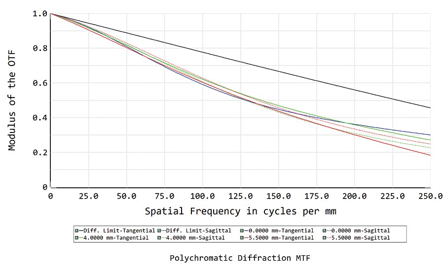
↑ Figure 3: A high resolution 25mm lens’s MTF at different settings. The same lens can have very different performance curves. ↓
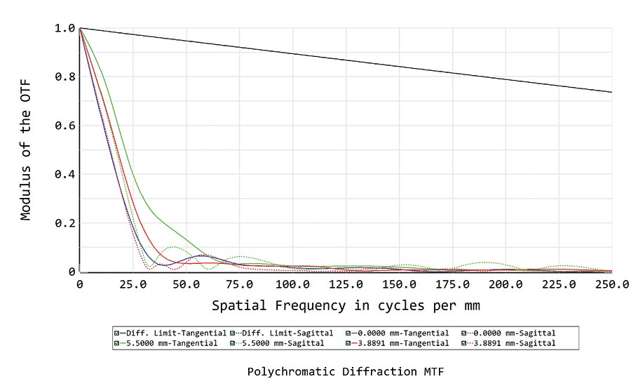
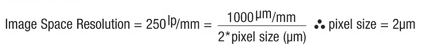
Based on the MTF of a given lens, the minimum resolvable feature size in object space can be determined. However, MTF curves are always in image space, which means that the image space information must be transformed into object space information. Luckily, this is as simple as scaling by the magnification. The following example illustrates how to do these calculations using the curves in Figure 3 as a starting point. Assuming a contrast minimum of 20% for this example, the lens on the left can resolve 250 lp/mm in image space, which is determined by finding the frequency on the curve that matches 20% contrast. Using Equation 5,
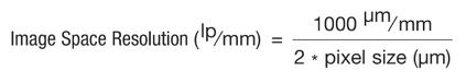
the pixel size (or in this case, the image space resolution converted from a frequency to a physical object) is calculated to be
and scaling by the magnification (0.076X),
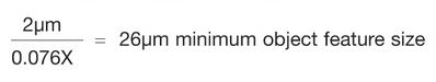
In comparison, the lens with the curve on the right of Figure 3 can only confidently image an object that is 282µm in size (using the same math as the above example).
Twenty percent contrast was chosen as the limiting contrast in this example, but it is generally the absolute minimum contrast that is recommended for lenses to say with a high confidence that the object will be resolved. This 20% limit allows for camera sensor noise variation, as well as lens to lens variations.
The above example assumes that the exact camera/sensor has not yet been chosen, therefore making the optics the limiting component in the imaging system. If a camera sensor has been chosen prior to the lens, the lens just needs to be able to resolve the pixel size of the sensor in use. Continuing from the example above, if a camera had been chosen which contained the Sony IMX250 sensor with 3.45µm pixels, using equation 2.1 it can be found that the image space resolution is 144.9 lp/mm. Looking at the MTF curve, the lens achieves >40% contrast there, which is more than enough for most applications. However, using the same calculation as in the above example to scale into object space, 3.45µm pixels only corresponds to a 45µm object, meaning the sensor would be the limiting component in the system, as the lens is capable of 26µm object space resolution. All of these considerations must be made when determining the proper lens for a given application in order to find the optimal solution to a machine vision problem.
A common way that minimum resolution is often calculated is by “projecting” the image sensor into object space and seeing how much space a pixel takes up in the field of view. For example, if a sensor had 1600 pixels in its horizontal dimension and the horizontal FOV was 100mm, then each pixel would take up 62.5µm. This is a great first-order calculation to perform to see if the imaging system is in the right range, but comparing the actual pixel size to the MTF of the imaging lens is still incredibly important; if the lens cannot resolve the individual pixels, then the lens will not resolve the 62.5 µm/pixel that the calculation results in.
Lenses are quite complicated analog components in an imaging system, and with sensors continuing to become better, with smaller pixels and larger formats, the lens’s role in the imaging system is more critical than ever before. Understanding the performance impact of a lens on an overall imaging system is vitally important to a successful system integration; giving time to the selection process of a lens will ensure the best performance possible. V&S
Looking for a reprint of this article?
From high-res PDFs to custom plaques, order your copy today!


