Deciphering Lens Specifications and Choosing the Proper Lens
In the past, cameras were once the limiting component for performance in and imaging system. Today, lenses have become the critical component in many applications.
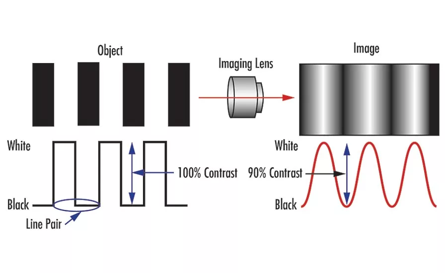
Figure 1: Contrast of a bar target and its image in which the edges of the bars are still clearly defined
Imaging and machine vision are becoming more integrated into our daily lives. From autonomous vehicles to advanced medical diagnostics, camera and lens systems are now commonplace. As sensor technology advances, pixel sizes on cameras have been getting smaller and sensors have gotten larger. In the past, cameras were once the limiting component for performance in an imaging system. Today, lenses have become the critical component in many applications. Even the latest smartphones have had to overcome this limitation by implementing a multiple lens solution. Understanding and choosing the right imaging lens has become more important than ever before. This article will explore imaging lens specifications, their importance, and how they apply to imaging applications today.
There is no silver bullet to choosing the right imaging lens for an application. Some specifications are more obvious than others, such as wavelength. While many imaging applications are in the visible range, other wavelengths are becoming increasingly more common. But even a specification as seemingly simple as wavelength is not truly simple. While there are imaging lenses that have been specifically designed and optimized for specific wavebands, such as the shortwave infrared (SWIR), other lenses are simply visible lenses that have been re-coated and sold for use at that specific waveband. This can greatly affect both the performance and cost of the end product—this subtle marketing difference can actually be significant. Even in the visible spectrum, wavelength is an important specification to consider. It affects many other lens specifications and understanding how is key. This type of change is most common in SWIR lenses, and recoated lenses drastically underperform when compared to lenses bespoke for the SWIR waveband.
Resolution is the specification that gets the most attention as megapixels are increasing and pixel sizes are getting smaller. It is helpful to understand how resolution is specified and tested. Simply put, resolution is the smallest feature size on an object an imaging system can resolve. Resolution is usually specified in line-pairs per millimeter (lp/mm) at a contrast percentage. The resolution of a lens is its ability to reproduce object detail onto a sensor. The more line-pairs in a millimeter a lens can resolve, the smaller the resolvable feature size, and the higher the resolution of the lens (Figure 1 and Figure 2). Contrast can be thought of as the “crispness” or “sharpness” of the line-pair or feature and it’s usually specified as a percentage. The modulation transfer function (MTF) curve is a mathematical representation of how a lens reproduces contrast as spatial frequency (or lp/mm) varies.
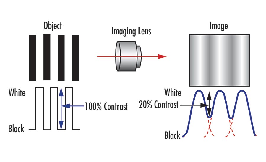
Figure 2: Contrast of a bar target and its image in which the contrast between bars only reaches 20%, making it difficult to clearly distinguish the features.
Resolution can be affected by other specifications such as f/# and wavelength. F/# increases as the aperture is stopped down, usually by closing down the iris. A smaller f/# typically means higher resolution since the diffraction limit of the MTF increases. The diffraction limit can be thought of as the highest performance a lens can achieve according to the laws of physics. The logical assumption would be to always use the smallest f/# possible all the time. But as the f/# decreases, lens performance becomes less limited by the diffraction limit and more affected by optical aberrations. At some point, decreasing the f/# will stop improving the resolution and start reducing the resolution as performance becomes dominated by optical aberrations. This point of diminishing return on performance can vary depending on the optical design of the lens. The design f/# of a lens is often not published by lens manufacturers and can have a large impact on the performance, size, and cost of the imaging lens.
There are a great number of optical aberrations that lens designers have to contend with. There are many levers that designers and engineers can push and pull to achieve the desired performance. One of these levers is wavelength and a large contributor to this is chromatic aberration. Axial color (chromatic focal shift) occurs when different wavelengths of light have different focus positions along the optical axis. Lateral color occurs when different wavelengths of light focus to different points on the sensor, causing the image to appear blurry. This effect occurs irrespective of whether a color or monochrome sensor is used. Whenever possible, using one wavelength of light is best, as monochromatic systems eliminate the issues of chromatic aberrations. In addition, the specific wavelength of light chosen can be important. Similar to how f/# can affect MTF, wavelength can as well. Using shorter wavelengths of light, such blue light, instead of the traditional red light, can provide higher resolution, since they diffract less.
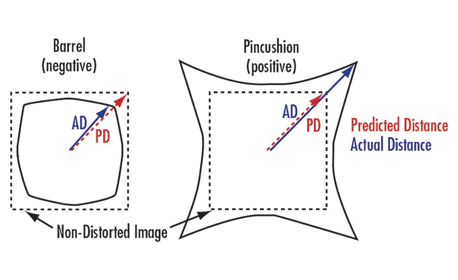
Figure 3: Depiction of the two main types of distortion: barrel, or negative, distortion and pincushion, or positive, distortion.
Another drawback to smaller f/#s is a reduced depth of field (DoF). DoF refers to the object distance or depth through which an object can still appear in focus. If the object placement can’t be well controlled, like in many barcode scanning or logistics applications, a higher DoF may be necessary. In these cases, a tradeoff is made between resolution, f/#, and DoF. Understanding how different optical specifications affect each other is important for properly specifying an imaging system.
A lens specification that is not commonly thought of as related to resolution is distortion (Figure 3). Distortion is the misplacement of object information on the image and is usually specified as a percentage of the image height. Since the information is not lost and just misplaced, distortion can usually be calibrated out by software. Depending on how much distortion there is, calibration can be slow and time consuming. In applications like electronics inspection, where multiple images are being stitched together and speed is important, a low distortion lens may be more suitable. However, low distortion lenses for large field of views (FOV) can be difficult and more complex to design. This why shorter focal length lenses typically have higher distortion. There is a tradeoff between distortion and design complexity, which can affect resolution, size, and cost.
Understanding how distortion is being specified is equally important. Distortion can be specified as either geometric distortion or CCTV distortion, and they are not comparable. Depending on the object and feature of interest, it is important to understand which type of distortion a lens supplier is specifying. In addition, the change in distortion across the image can be non-linear and may even change from positive to negative across the image (Figure 4). Distortion is also wavelength dependent. In some applications, just knowing the distortion percentage may not be enough information to fully understand the distortion in an imaging lens, since that percentage will vary based on the position on the sensor.
All of the specifications and performance criteria discussed above have been in reference to nominal design performance. Nominal design performance can differ greatly from real-world performance. Nominal design performance does not take into account manufacturing and assembly tolerances. It assumes every component in the lens has been manufactured perfectly. Usually, lens suppliers do not publish their real-world performance data. Because it can vary depending on the sensor size, wavelength, working distance, field of view, and many other parameters, it can be difficult to present a complete view of a lens performance for all applications. Understanding that nominal design performance can be different from toleranced design performance, which can be different from tested performance, is important when discussing specification requirements with a lens supplier. It is much easier to supply a well-performing lens one time than it is to supply multiple well-performing lenses consistently each time. Making sure your lens supplier understands how to design for manufacturability and how to test critical specifications ensures a successful project.
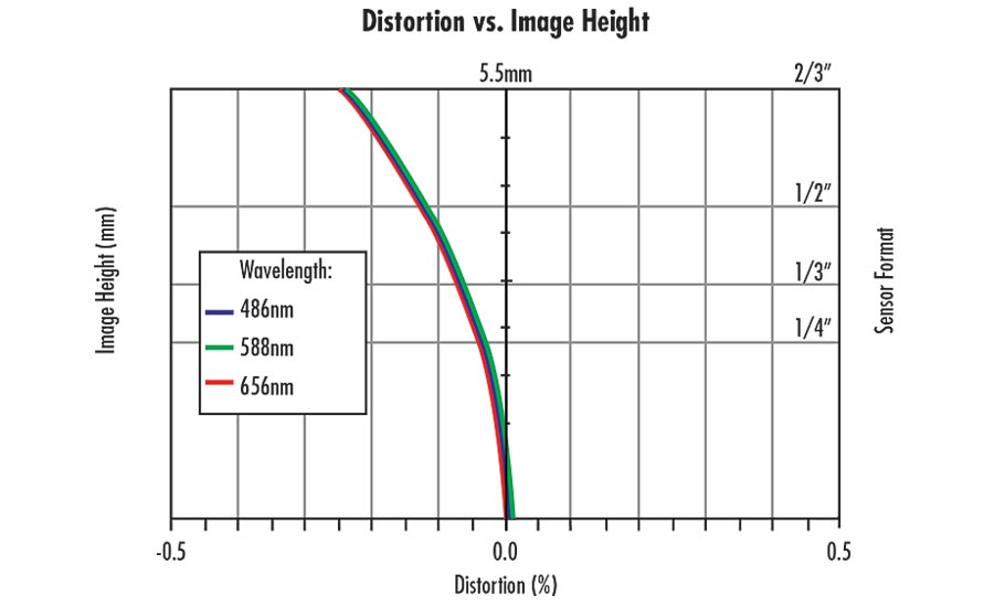
Figure 4: For this lens, distortion changes from positive to negative depending on the image height.
The manufacturing and physical properties are sometimes equally as important as the optical properties. As more lenses are being used outside of traditional factory automation applications, the term “ruggedized” is being used more often. But ruggedization is a term that is very loosely defined in the industry. A specification of 50G shock and vibration is not helpful if it doesn’t specify what lens performance is maintained after the shock and vibration. Does it refer to survivability, MTF maintenance, calibration, or pointing stability maintenance? Survivability may be insufficient for some applications. The term ruggedized is also used to describe ingress protection, where a lens is sealed against dust and water in the environment. These are two very different types of ruggedization. Ruggedization from shock and vibration may be more important for calibrated applications like 3D metrology, and ingress protection may be more important for food and beverage applications where the lens may need to survive a wash-down environment. Both may potentially be needed like in some autonomous systems or agriculture applications.
Working with a lens supplier who understands lens specifications, their tradeoffs, and how they pertain to specific applications is important to a successful project. As the applications for optics and imaging expands, lens solutions will continue to face new design challenges. Customized lens designs can be costly and time consuming. To find the right lens solution, it is important to first understand what specifications are truly needed. V&S
Looking for a reprint of this article?
From high-res PDFs to custom plaques, order your copy today!


