Understanding the Role of Load Cells in Force Measurement
This will help you choose the most appropriate load cell for your application.

Load cells are an integral part in a force measurement system. Understanding load cell terminology, common sizing techniques, and how they function will help you choose the most appropriate load cell for your application, which will help prevent accidental damage due to an incorrect selection.
Load cells are an integral part in a force measurement system. Understanding load cell terminology, common sizing techniques, and how they function will help you choose the most appropriate load cell for your application, which will help prevent accidental damage due to an incorrect selection.
Terminology
Load is a common term used in place of a force exerted on a surface or a body. It is often expressed in either N (Newton, 1 kg * m/s2), LBF (pounds force), KGF (kilograms force). On a force measurement machine, load is measured with a load cell sensor.
Full Scale or Capacity is the maximum axial load a load cell sensor is designed to measure within its specification. Load cells have a safe overload percentage.
Axial Load is the load applied to the primary axis. Sensors have a “live” side, e.g. the side where load is to be applied. Incorrect loading will result in erroneous readings. Most manufacturers provide intuitive ways of ensuring that the load cells are mounted correctly.
TEDS stands for Transducer Electronic Data Sheet. TEDS-enabled load cells call for the load cells to be self-identifying and “plug and play.” In turn, it helps minimize system setup time when swapping load cells by storing information such as sensor calibration data, load cell capacity, and overload history.
Full Scale Deflection is the mechanical deflection produced by the load sensor when maximum (full scale) load is applied.
Choosing a load cell for your application
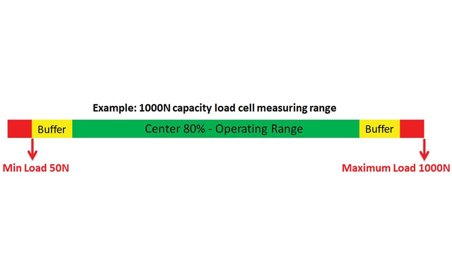
When selecting a load cell, choose one that allows operating in the middle 80% of the sensor’s capacity. To ensure accurate readings, never use a sensor to measure force below 5% of the sensor’s rated capacity. Leaving a buffer on the top end of the scale helps protect the load cell and allows parts to be run if they turn out to be slightly stronger than expected. Most new systems read the load cell capacity directly from TEDS chips and will stop when they hit the load cell’s capacity.
Double check your units! When sizing a load cell, verify that units are not expressed as a pressure, for example:
PSI (pounds per square inch) OR Pascal (Pa)
If the units are in PSI or Pa, the area of the sample will need to be taken into account when sizing a load cell.
Addressing load cell deflection
All load cells deflect when load is applied. Most force systems offer deflection compensation where the deflection in the load cell, grips, and the test frame can be compensated. During any kind of compression or tensile testing, deflection occurs. However, there are some differences:
- The sample may or may not deflect
- The load cell will definitely deflect
- The test fixture will very likely deflect
- There is deflection within the test frame column, crosshead and internal mechanisms.
Load cell sensors deflect by design. It is the deflection of the load cell that allows the load cell sensor to measure accurately. A full-bridge strain gage will generally provide better measurement performance over a half-bridge design. The deflection changes the shape of the load cell and the bridge, which produces a resistance change that corresponds to a load measurement.
Test fixtures deflect. Even very stiff compression platens will deflect when under a load. Wedge and vise-action test fixtures will deflect in tensile testing.
Test frames are inherently rigid with minimal deflection. There will likely be some mechanical deflection when testing under a load. The higher the load, the more opportunity for deflection.
These system deflection effects may be important to the measurement of the sample. If so, it is imperative that all deflection from all components used in the test are compensated for, including the load cell, grips, and test frame. Incorporating all three in the correction provides a more accurate measurement of distance, heights and strain (when not using an extensometer). Most force systems have deflection compensation that can be entered as a correction factor.
Preventing load cell damage starts when the load cells are being installed to support the live end of the load cell, and when tightening clevis adapters or attaching grips.
Use adjustable “over travel limits.” “Over travel limits” serve as the boundaries for where a crosshead can move and are a first line of defense in protecting a load cell. For example, in a tension application there should be no need for vise fixtures to touch. Set the lower limit so that the two fixtures cannot accidentally run into one another.
These force measurement systems are designed with the load cell mounted below the crosshead. If the Starrett logo is right side up, it is in the correct orientation with the live end facing the application.
Software Limits
A “STOP IF” condition is a software limit within an individual move step. Selecting the STOP IF function presents you with options for terminating a test.
There is additional software functionality that could limit the capacity of your test system. The “MAXIMUM LOAD ALLOWED” feature enables limiting the capacity of a connected load cell sensor across the software by specifying the maximum load allowed. Using this limit can help prevent accidental overloads. If using a 100N load cell, and specifying the Max load allowed at 75%, the 100N load cell will measure between 0 and 75N. A test run will terminate if this load limit is exceeded.
A “GRIP LOAD” is a value that may be entered to protect the test fixture (grip) from damage due to overloading or exceeding the load capacity of the test fixture. All test fixtures have a load capacity. This load capacity is the maximum load that the test fixture is rated to handle. Exceeding this capacity can permanently damage the test fixture. For example, adjustments to the GRIP LOAD should be made when using a 1000N load cell with a test fixture having a maximum testing capacity of 50N. In order to protect the test fixture, set the GRIP LOAD to 50N. When 50N is reached, the test run will terminate and protect the test fixture.
Often, the maximum capacity of the test fixture is below the maximum load capacity of the load cell sensor, therefore, the maximum load for a test setup should be the lowest rated capacity of the test fixture, load cell or test frame.
However, use caution when operating load cells, especially at high speeds and particularly in compression directions. Enabling STOP IF conditions, MAX ALLOWED LOAD percentage, and GRIP LOADS all help protect against load cell overloads but will not guarantee they won’t happen. A challenging application is excessive crosshead speed which may make it impossible to stop in sufficient time to prevent an overload.
Consulting your force system manufacturer and/or supplier experts is highly encouraged in order to optimally set up load cells for the application at hand. Q
Looking for a reprint of this article?
From high-res PDFs to custom plaques, order your copy today!


