How Proper Specification of Load Cell Sensors Can Improve Force Measurement
Accuracy is only one of many characteristics that should be examined before selecting a sensor for an application.
The load cell sensor is arguably the most important component in a force measurement or material testing system’s ability to provide accurate, precise and valid measurements. A sensor’s accuracy is often the primary characteristic that is used to specify a load cell sensor for a given application. However, accuracy is only one of many characteristics that should be examined before selecting a sensor for an application. Full scale capacity, deflection, resolution, alignment, operating environment, test method(s) employed, and operator experience are also factors that should be examined and carefully analyzed before selecting a load cell sensor for an application. Having an improper load cell sensor can yield invalid results and compromise the testing method and measurement system. The following identifies some additional sensor characteristics that should be used to specify the best solution for the application in question.
Sensor Capacity
There are a number of characteristics that should be understood when evaluating the load capacity needed for the application. A load cell’s minimum dead load is the lowest load that can be measured by the sensor and meet the sensor’s specified performance. The measuring range is the area where the load cell should be operated. As a general rule, it is recommended that a sensor be specified to operate within 10% and 90% of its full-scale rating. Noise and error effect can compromise the measurement below 10% full scale. Operating above 90% can lead to accidental overloading. The maximum safe load is the load that may be applied without causing a permanent shift in performance and permanent damage to the sensor. Overload protection can help avoid overload conditions. However overloads that occur due to over-travel at high velocity or mishandling of a sensor, especially very light sensors, cannot be reliably protected. The most common reason for overload is human error. (See Figure 2.)
Zero Balance
Zero balance is the signal of the load cell when there is no load condition. Laying the load cell on its side should represent the zero balance. Very light load cells, when suspended in their normal vertical position, will display load due to the gravitational effects from the sensor’s mass.
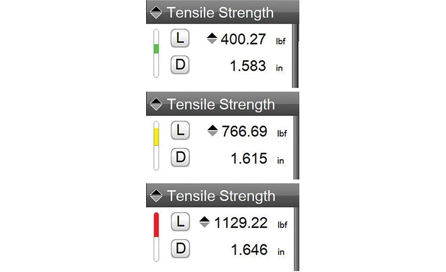
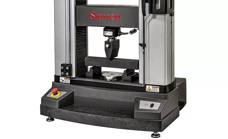
Figure 1. A full range of precision load cell sensors are available for material testing, force analysis and force measurement applications.
A visual indicator of a load cell’s measured load:
Green: Operating in Normal range - 0 to 80%
Yellow: Operating in Caution range - 81 to 95%
Red: Operating in High range - above 95% Full Scale
Taring
Mass due to gravity and the weight of the attached test fixture should be zeroed or tared prior to testing. How much tare available is dependent on the manufacturer. Traditionally, a 10-15% tare was allowed because the mass, if it exceeds that 15% limit, consumes that much of the sensor’s full-scale capacity. More advanced force measurement software can allow higher tare values to be used. As a general rule, the tare amount plus the live load measurement by the sensor should be less than 1.5 times the load cell sensor’s full-scale capacity.
Accuracy
Accuracy is often expressed as a percent of full scale. The error effect has less impact on the load measurement the closer the measurement is to the full-scale capacity of the sensor. Conversely, the error will have a greater effect the closer the measurement is to zero. When testing with a load cell sensor that has too high a capacity at a low load, the error effect on the measurement can be considerable. Testing below 10% of the sensor’s rated capacity should be avoided.
Resolution
Resolution is the detectable change in load that can be measured by the load cell. Resolution is dependent on the stability of the electronics being used to measure the signal from the load cell to the ultimate digital readout instrument. Resolution is more dependent on the electronic signal received than by the load cell sensor’s signal output.
Full-Scale Deflection
Load cell sensors are designed to deflect. As load is applied, the deflection causes changes in the sensor’s internal resistance. But deflection can be a detriment to distance or height measurements, especially in components such as springs. All sensors have a full-scale deflection characteristic. In spring applications, it is typical for proper testing to compensate for the deflection amount. More advanced testing software will allow for deflection compensation, resulting in more accurate and precise measurements of distance/heights.
Alignment & Test Methodology
Load sensors used for force measurement and material test are designed to operate axially. The load string should be perpendicular, and each component of the string should be axial to one another. Even a very small offset on a load cell can contribute significant measurement error. Load sensors also have a “live” and “dead” side. The “live” side is the measurement end, and improper orientation can result in measurement error caused by the mass of the cable used to connect the sensor to the test system.
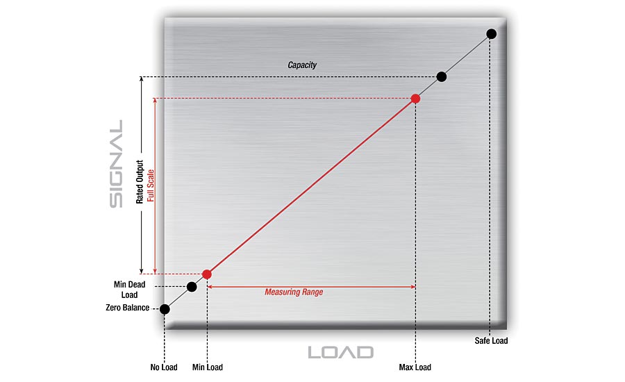
Figure 2.There are a number of characteristics that should be understood when evaluating the load capacity needed for the application.
Operating Environment
Load cells are electro-mechanical devices subject to temperature effects. A load cell should always undergo a warm-up period before being used. Fifteen minutes is recommended. Today’s load cells will typically be temperature compensated. However, direct sunlight on a load cell can impact the sensor’s performance. Operating in a high temperature environment can affect signal resistance, including the sensor’s cable response to temperature change effects and thermal span characteristics.
Overloads and Operator Experience
Today’s force measurement systems have features that help prevent sensor overloads. The majority of sensor overloads are due to operator error. For example, the user caused the overload by not understanding the sensor’s performance, the test method application, or due to simple misuse and neglect. Many systems or instruments provide visual indication of where the measured load is relative to its capacity. Some systems feature load scaling that creates an operating range for the sensor that is within the full-scale range of the sensor. Travel limits on test frames stop crosshead travel and help reduce sensor overloading. However, it is critical that users understand what the full-scale deflection means for the sensor and what the associated travel limitations are. Additionally, with motor-driven systems, it is equally important to understand that a crosshead, moving at a high velocity is incapable of stopping immediately when it comes into contact with a hard object. Finally, low-capacity sensors can overload and become permanently damaged by a user improperly handling the sensor. (See Figure 1.)
Conclusion
Understanding all of the basic performance characteristics of a load cell should be factored when specifying a sensor for an application. Simply selecting a sensor based on its full-scale measurement capability or measurement accuracy is not enough. For better measurements and to ensure you have the correct sensor for your application, it’s best to let the sensor supplier verify a selection prior to making a purchase.
Looking for a reprint of this article?
From high-res PDFs to custom plaques, order your copy today!


