VISION & SENSORS - LENSES
Protecting Lenses
Imaging systems have specific design requirements to maintain performance without degrading over time.
Opening Images Source: yoh4nn / E+ and Cobalt88 / iStock / Getty Images Plus viaGetty Images.
Imaging lenses enable machine vision systems to inspect, sort, and measure objects for a variety of applications including manufacturing, robotics, autonomous (self-driving) vehicles, and more. Many of these applications are conducted in harsh environments with some form of hazard or danger. Standard-model imaging lenses designed for less demanding applications are sometimes too fragile or frail to withstand shock and vibration, water and humidity, particles of dust and debris, or large changes to temperature, factors that contribute to harsh environments.
Imaging systems in these environments have specific design requirements to maintain performance without degrading over time. One of the most effective ways to ensure imaging system performance in such environments is to use a lens that has been designed and manufactured for these harsh environments, such as ruggedized or athermalized lenses. However, these specially designed lenses come at an expense to the end-user. Compared to standard imaging lenses, the user forfeits versatility and some degrees of application freedom and increased cost. Depending on the types of harsh environmental factors present in the application, the appropriate ruggedization type may be industrial ruggedization stability ruggedized, ingress protection, or athermalization.
Standards For Environmental Testing
Just as there are many different harsh environmental factors surrounding an imaging system and several different types of ruggedization, there many different standards for which ruggedized imaging lenses are tested against to ensure performance, durability, and application relevancy. A few of the most cited standards for the environmental testing of durable goods, both commercial and defense related, are the international IEC 60068 and 60529 standards and the United States military standard MIL-STD-810. All of these standards are collections of guidelines and techniques that are to be used for the testing of components in environments, which simulate the pertinent environmental factors for the use cases. The environmental factors considered in these standards include but are not limited to exposure to shock and vibration (acceleration); particles including sand and dust; moisture, humidity, and water; temperatures high, low, and shocking; and corrosion from salt fog. Because these standards were created broadly for many types of equipment and not solely for imaging lenses and systems, these standards should only serve as guidelines for ruggedized lens design and testing. It is important to consider the actual demands of the applications.
Shock And Vibration
Shock and vibration occur in many different application environments. They are common in manufacturing settings and on self-driving vehicles and robotics. Imaging lenses subjected to shock and vibration can become damaged in a number of ways. Shock and vibration can shift, decenter, crack, and chip the optical elements within an assembly. Retainers and the assemblies themselves can become unthreaded. The moving components within the assembly, such as adjustable irises and focusing mechanisms, are also common points of failure. All of these changes can aggregate to affect the f-number, resolution, and modulation transfer function. Imaging lenses experiencing too much shock or vibration can fail by falling apart in extreme cases. Depending on the application, a different type of ruggedization may be required for environments with shock and vibrations – industrial ruggedization or stability ruggedization.
Industrial Ruggedization
Industrial ruggedized lenses are designed and manufactured to survive shock and vibration and to not damage or shift focus or f-number during use. These lenses have optomechanical designs with a reduced number of movable and complex parts. Most of the movable mechanical features are replaced with a static analogue. Standard imaging lenses usually feature an adjustable iris composed of thin leaves and ball detents, which are used for adjusting the aperture size of the lens and therefore the f-number. The adjustable iris mechanism, which is present in a standard imaging lens, is replaced with a fixed aperture stop for industrial ruggedized lenses. This replacement eliminates the changes of exposing damage-susceptible parts to harsh conditions. This replacement also reduces application flexibility but makes the assembly easier to lock down, less likely to be inadvertently adjusted, and comes in the form of a reduction to the lens’ overall size.
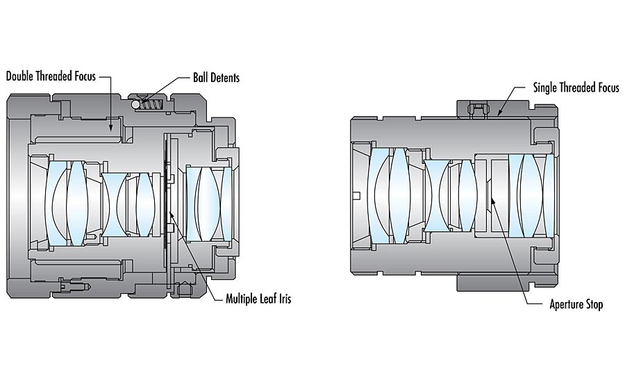
Figure 1. (l) A standard-model imaging lens with an adjustable iris. (r) An industrial ruggedized imaging lens with simplified mechanics. Source: Edmund Optics
Industrial ruggedization is ideal for applications where the imaging system is set up and left unchanged. Because static components are typically less costly than movable parts, a significant cost savings is achieved at volume and passed along in the form of a mechanically simpler, more robust product. There are numerous applications for industrial ruggedized lenses including high-vibration production-line environments where the camera is quickly accelerated or decelerated, inspection systems where multiple similar camera systems are set up, and autonomous systems such as self-driving cars and warehouse sorting robots.
Optical Pointing Stability And Pixel Shift
While shock and vibration may damage standard imaging lenses, to the point of failure, industrial ruggedized imaging lenses are built to withstand these effects by minimizing the number of moving parts and restricting the movement of remaining elements within the assembly. However, imaging systems that rely on highly accurate, repeatable performance and must maintain sensor calibration may fail in particularly high shock and vibration environments. Lens elements sit within the inner bore of the barrel of an imaging lens assembly. The bore gap between the outer diameter of the lens and the inner diameter of the barrel is around 20 microns or less. Though this gap is very small, decenters of only microns have substantial effects on the optical pointing stability of the lens.
Optical pointing stability is defined by how well an imaging lens is able to reliably and repeatably map points from an object of inspection to the corresponding points on the image produced by the camera sensor (Figure 2).
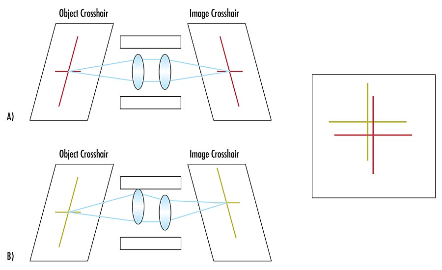
Figure 2. A: An unperturbed system without shock or vibration maps the object crosshairs to the image crosshairs. B: Lenses within the barrel of a system perturbed by shock or vibration can decenter causing a change in optical pointing stability. As a result, the object crosshairs are mapped to a different part of the image. Source: Edmund Optics
An imaging lens with poor optical pointing stability will map the corresponding points on the image sensor such that distance between these points will be of high variance. On an image sensor, this variance is called pixel shift. Optical pointing stability and pixel shift go hand-in-hand and have an inverse relationship (Figure 3).
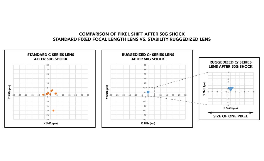
Figure 3. A: A standard imaging lenses experiencing 50G of shock has pixel shift greater than the size of one pixel. B: A stability ruggedized imaging lens with improved optical pointing stability (b) under the same conditions has less than 1 micron of pixel shift, which is much smaller than the size of pixel. Source: Edmund Optics
*Click the image for greater detail
Stability Ruggedization
For applications with shock and vibration that require highly accurate, repeatable performance, stability ruggedized imaging lenses are the ideal choice. Stability ruggedization is similar to industrial ruggedization in that both ruggedizations protect the lens assembly from damage. In addition to having the adjustable iris and movable focus mechanism removed, stability ruggedized lenses are further stabilized by gluing down all internal lens elements and by adding a clamping lock to simplify the focusing mechanics (Figure 4).
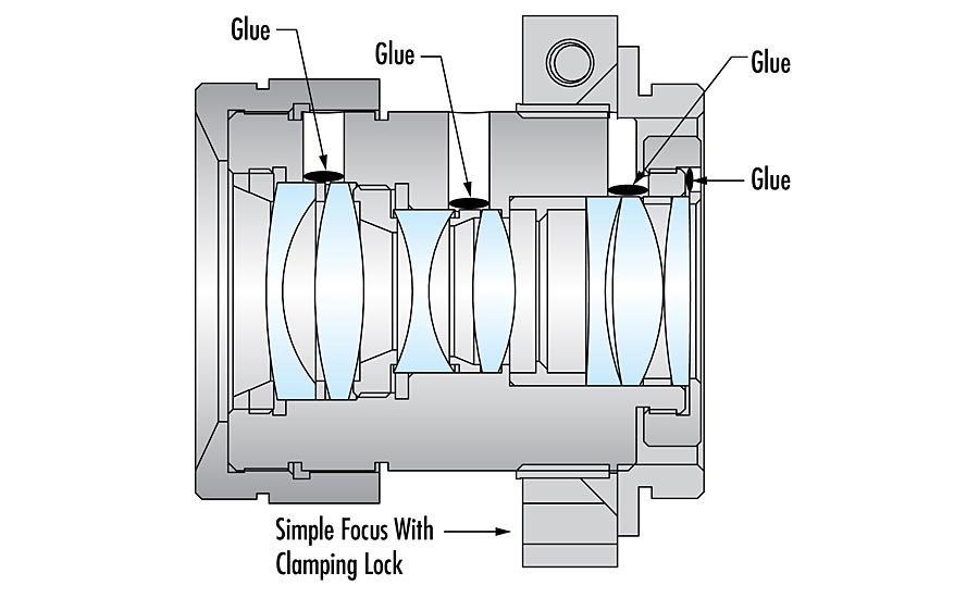
Figure 4. A stability ruggedized lens assembly is composed of optical elements that are all glued in place. Source: Edmund Optics
The improved optical pointing stability of these lenses ensures that the pixel shift these lenses experience is smaller than the size of a pixel on most sensors (Figure 3). Stability ruggedized lenses are ideal for high-accuracy measurement including 3D stereo vision, machine vision sensing for robotics, and the tracking of the locations of moving objects.
Water And Particles
Ingress protection (IP) ruggedization is used to seal the imaging lens away from external factors such as moisture or debris particles. Because of the susceptible nature of complex movable components to moisture and other factors, ingress protected lenses are often also industrially ruggedized as well. Additional ingress protections come in the form of O-rings or RTV silicone applied to susceptible points within the assembly and hydrophobically coated windows and/or lens elements (see in Figure 5).
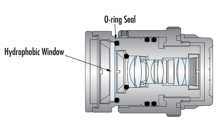
Figure 5. An ingress protected ruggedized lens features an O-ring to seal out contaminants like dust, dirt, or moisture and a hydrophobic window in the front. Source: Edmund Optics
Ingress protected lenses are given a two-figure rating. The first figure gives the amount of protection against the intrusion of particles and ranges from 0 to 6. It is somewhat difficult to accurately test imaging lenses for protection against particles. As such, the first figure in the rating is sometimes reported as X, indicating that the lens has not been explicitly tested for particle intrusiveness. The second figure denotes the amount of protection against forms of moisture and water and ranges from 0 to 9, or 9K. Most ingress protected imaging lenses today are thoroughly tested for protection against water submersion and washdown with close-range high-pressure water spray. These lenses typically feature a rating of IPX9 or IPX9K (with or without further particle protection specified).
Ingress protected imaging lenses are a cost-effective, space-saving alternative to applying a protective enclosure around the entirety of an imaging system—lens, camera, and all—which may ultimately be very costly depending on the geometry of the system and angular field of view of the lens. Additionally, users may opt to use an enclosure along with ingress-protected lenses such that the ingress protection is used as a layer of redundancy. However, protective enclosures are large and cumbersome and may prevent the user from being able to refocus the lens while operating.
Temperature Changes
Mechanical Effects
As temperatures fluctuates, different materials expand and contract at different rates, indicated by a coefficient of thermal expansion (CTE). Imaging lens assemblies are typically made from aluminum metal, which contrasts faster than glass since aluminum has a larger CTE than most glass. At extremely low temperatures glass lens elements can crack due to the compressive stress from the aluminum shrinking faster than the glass. At the other extreme, the housing will expand faster than the glass as temperature increases. The housing expanding faster than the glass, increases the bore gap, and can affect the optical pointing stability.
Optothermal Effects
Changes in temperature additionally affect the refractive indices, radii of curvature, and thicknesses of lens elements. Most spacers are made of aluminum and changes to spacer thickness impart changes to the size of the airgap. Changes in the air gap and lens element dimensions result in chromatic and thermal defocus effects within the lens causing significant performance degradation. In a standard non-athermalized lens, the focus can change with wavelength and temperature variation. Thus, changes to system resolution and performance should be anticipated. If the user does not have the ability to refocus or compensate for these performance changes, a standard imaging lens may not be appropriate for the application. To combat degraded performance, athermalized lens designs over a specified waveband and temperature range take into consideration: changes to refractive indices of the glass types (dn/dT) of the lens elements, the thermo-optic coefficients of the lens elements, and the CTE of all the materials used. Athermalized lenses ensure that chromatic effects and changes to the focus are minimized.
Imaging lenses are used in such a wide range of machine vision applications that designs for ruggedization techniques are numerous. It is extremely important to specify the application type to optical designers or the lens manufacturer as early as possible to manage the expectations for the lens in the system. Lenses to be used in particularly harsh applications can be designed for protection against numerous types of harsh environmental factors. However, because temperature effects usually cannot be resolved or compensated for in situ, thermal effects must be managed at the earliest stages of optical design. Subsequent mechanical techniques for ruggedization (industrial, stability, and ingress protection ruggedization) can then be applied in later phases of the optical design and are typically easier to apply to (standard) imaging lens designs for additional environmental protections.
References:
IEC 60068-2. (n.d.). Retrieved January 27, 2021, from Desolutions.com website: https://www.desolutions.com/testing-services/test-standards/iec-60068-2/
IEC 60529 ingress protection expertise. (2013, August 21). Retrieved January 27, 2021, from Cvgstrategy.com website: https://cvgstrategy.com/iec-60529/
Olson, C. (2012). Field guide to lens design. Bellingham, WA: SPIE Press.
Schwertz, K., & Burgw, J. (2012). Field guide to optomechanical design and analysis. Bellingham, WA: SPIE Press.
U.S. Department of Defense. (2000). Test Method Standard for Environmental Engineering Considerations and Laboratory Tests. Retrieved from U.S. Department of Defense website: http://everyspec.com /MIL-STD/MIL-STD-0800-0899/download.php?spec=MIL_STD_810F.949.pdf
Looking for a reprint of this article?
From high-res PDFs to custom plaques, order your copy today!


