Quality 101
Cylindrical Ring Gages: One Ring to Rule Them All
Cylindrical ring gages may be used as master gages to set variable measuring tools.
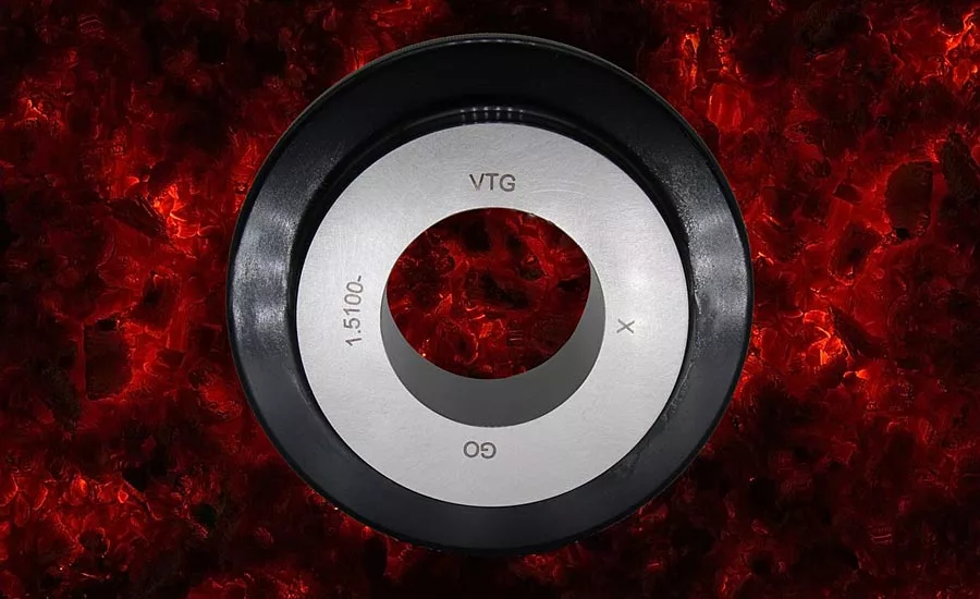
Image Source: Nastco / iStock / Getty Images Plus via Getty Images.
Cylindrical ring gages have a number of inspection purposes. They are used as Go/No-Go gages to inspect the outside diameter of a shaft or rod. They are masters for dial bore gages, internal micrometers and coordinate measuring machines (CMMs). They work well in applications where functional maximum material condition inspection of a shaft or other outside diameter is required.
In the United States, cylindrical plain ring gages are fixed limit gages manufactured per ASME B89.1.6. This standard defines the dimensional and geometric tolerances for the cylindrical ring gages. See the Diameter Tolerance chart (Fig. 1).
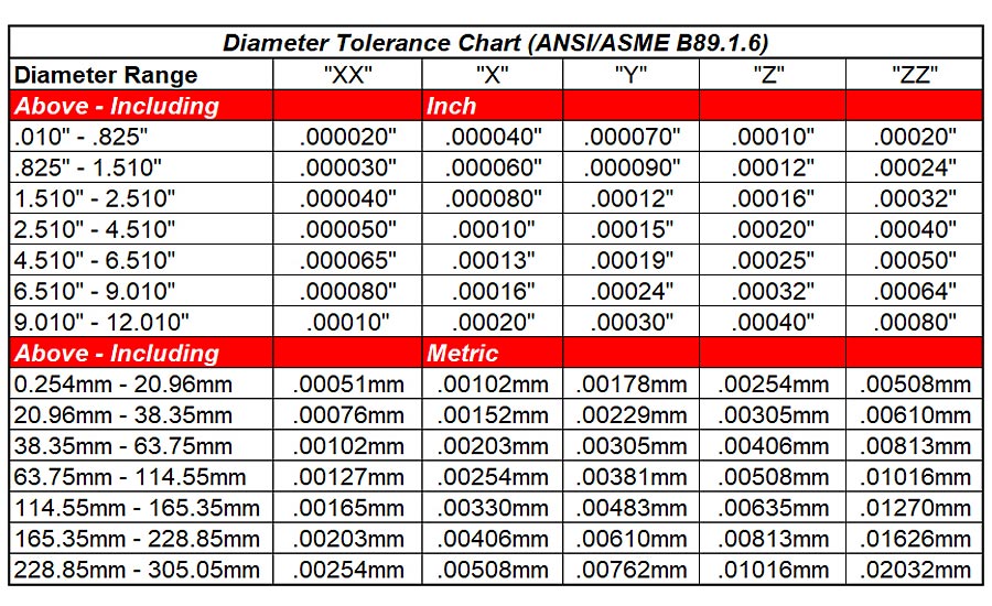
Figure 1. *Click the image for greater detail
Other key gage tolerances include surface finish, taper, roundness and straightness. The tolerance on the taper, roundness and straightness features are generally one-half of the stated ring gage diameter tolerance. This insures that the geometric features of the cylindrical ring gage will not adversely affect the outside diameter measurement of the part being inspected. See ASME B89.1.6 for the actual values.
Cylindrical plain ring gages may be used as a pass / fail inspection tool to inspect outside diameters. If the Go ring fits and the No-Go does not, the part outside diameter is in tolerance. The selection of the Go and No-Go gage diameters and the tolerances can be challenging. This is where guides such as the “10% Rule” become helpful. (See ASME B89.7.3.1 for other guard banding options.) Typically, the user selects the gage diameter and tolerances based on the gages using no more than 10% of the total product tolerance. (Fig. 2)
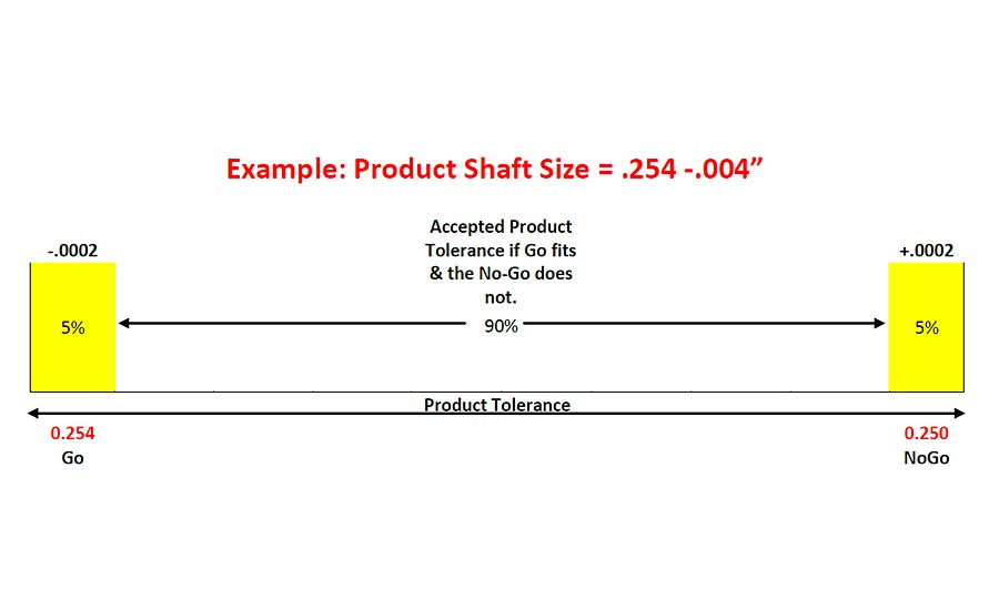
Figure 2 *Click the image for greater detail
The Go ring gage represents the maximum diameter of the outside diameter of a shaft or rod. The tolerance on the Go ring gage is applied, minus. The No-Go ring represents the minimum outside diameter. The gage tolerance is applied, plus. The No-Go ring gage has a groove ground into the outside diameter. This groove is used as a visual indicator that the ring is a No-Go cylindrical ring gage. The Go and Master rings do not have a groove on the OD. (Fig. 3)
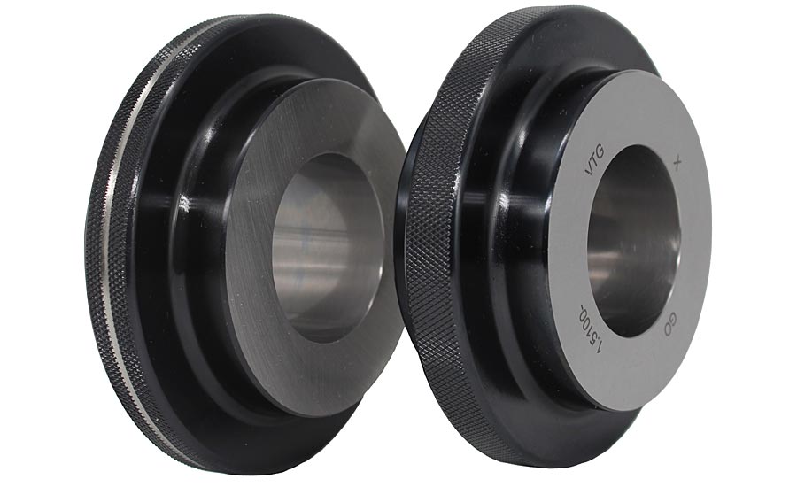
Figure 3.
Cylindrical ring gages may be used as master gages to set variable measuring tools. One calibrated master ring may be used to set multiple variable measuring devices. Master ring gages are typically ordered with a calibration certificate stating the actual calibrated internal diameter. This actual calibrated diameter allows the user to set their variable measuring or metrology device to the calibrated diameter. Once the variable device is set to the calibrated ring, the deviation from the master may be accurately recorded.
The measuring device being set may have an influence on the life and the requirements for the master ring gage. Using a cylindrical master ring gage to set a coordinate measuring machine (CMM) may require the face of the ring to be perpendicular to the internal diameter to eliminate or lessen the cosine error. Many universal length measuring (ULM) devices have tilt tables to help to adjust for cosine errors. Bore gages and other types of ID micrometers have two (at 180°) or three (at 120°) contacts. The contacts on these ID micrometers and bore gages only touch the internal diameter of the ring gage in specific zones. This may cause greater wear in these contact areas. To reduce the impact of this wear, many customers use carbide cylindrical master ring gages. The carbide material in the ring gage has a higher wear resistance than a steel ring gage of the same size and tolerance. If the ID micrometer or bore gage has carbide contacts, the use of a carbide ring gage (Fig. 4) may extend the life of the master ring gage. Carbide ring gages may be preferred for high volume inspection on abrasive materials or product tolerances that require close gage tolerances, usually Class X or XX.
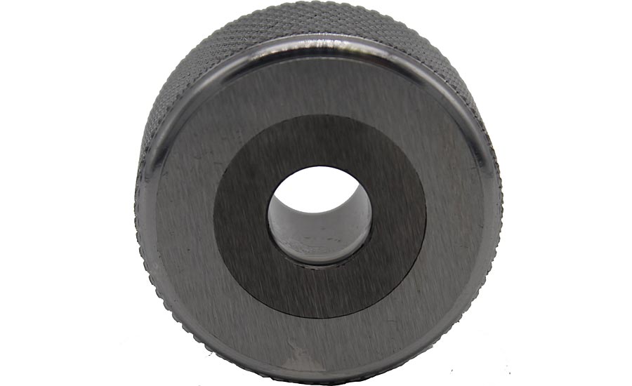
Figure 4.
Go cylindrical ring gages are functional inspection tools. They may be used to confirm maximum material condition (MMC) specifications of the outside diameter of shafts and rods. Using the Go ring in this manner complements the use of variable gages such as calipers and micrometers. The variable gages are good for measuring part-to-part deviations. The variable gage allows the user to make diameter adjustments while in the process of manufacturing the outside diameter of their part. The Go cylindrical ring represents the maximum material condition of the outside diameter of the part. If the part passes the two-point micrometer or caliper but does not pass the Go ring gage, the part fails at maximum material condition. This failure may indicate that the part is out of round. Two point measurements do not pick up geometrically odd sided or lobed parts. The Go ring gage represents the functional maximum diameter. The Go ring is required to have the roundness and taper within one-half of the total gage tolerance. A Go Class X cylindrical ring gage at 0.250” diameter will have a diameter tolerance of .250” -.000040”. The roundness for this gage is .000020” per ASME B89.1.6, table 2. If the part fits the Go ring gage, the outside diameter of the part is confirmed to be functionally smaller than the maximum material condition.
Cylindrical ring gages work well as a functional complement to variable gages, as stand-alone pass / fail functional inspection tools or as a master to set other gages. As with all gages, they need to be handled with care. Using dirty, damaged or out of calibration gages will greatly affect the products they inspect. This becomes a larger problem when ring gages are used as masters to set other devices. While a calibrated master ring may be used to set a number of other measuring devices accurately, the use of one out of tolerance or damaged master will affect any device it is used to set. Take care of your gages and they will take care of you and the products you produce. Q
Looking for a reprint of this article?
From high-res PDFs to custom plaques, order your copy today!


