Vision & Sensors | Lighting
Three Challenges In Machine Vision Lighting Today And How To Solve Them
With increased speeds, dynamic production lines, and advanced inspection processes, smart automated lightng is driving machine vision solutions.
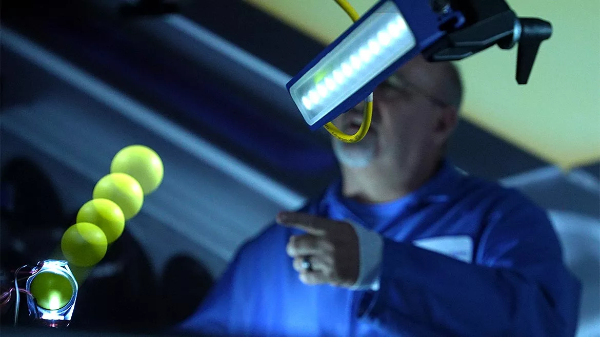
Image source: Smart Vision Lights
As machine vision technologies and capabilities advance, new applications inevitably emerge, helping end users increase efficiency and productivity in novel ways. One constant in the ever-evolving machine vision space is the need for high-quality, consistent lighting. New challenges in the design and specification of machine vision systems require an innovative approach to lighting selection.
Finding The Right Light Intensity
Due to industry demands, lighting options must expand to accommodate increasing speeds, resolutions, and advanced applications. These demands are often associated with less exposure time. To compensate, the best general solution is evenly distributed high-intensity lighting with short exposure times.
LEDs are a common, efficient, and intense light source that can solve these light intensity challenges. In noncontinuous applications, it is possible to pulse LEDs at higher currents to increase the output by three to eight times. This is commonly referred to as overdrive. Doing so provides greater light intensity but introduces a timing challenge. Providing full light intensity without image degradation requires precise control of the pulse rate and shape.
The ideal pulse shape for these fast shutter events is a square wave. Slow edges on either side of the pulse leads to motion blurring. To provide evenly distributed high-intensity light, LEDs must reach and maintain 100% intensity throughout the shutter cycle. External LED drivers may have parasitic impedances from wiring that contribute to broader pulses and sloped edges resulting in system jitter and blurred images. Internal LED drivers have fewer challenges reaching 0 to 100% and 100 to 0% intensity quickly. These fast on/off cycles create a square-like signal pulse shape that can closely match shutter speeds for better high-speed machine vision.
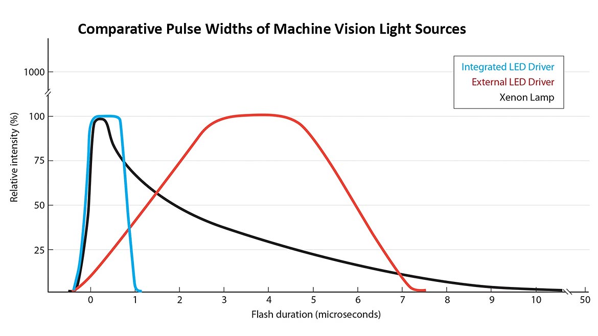
Figure 1: The pulse shape is just as important as its absolute intensity. While xenon lamps (black line) have comparatively higher intensities, only 10% of the light is effective due to poor pulse control. LED sources with external controllers (red line) show inescapable parasitic impedances often associated with external drivers. Integrated architecture with integrated drivers and controllers in close proximity on the motherboard (blue line) allows the LED to achieve full power in the 300–500 ns timeframe and to deliver repeatable, high-intensity pulses with durations in the microsecond range. Image source: Smart Vision Lights (Click on the image to enlarge.)
The pulse rate and shape are important in high-speed applications where every microsecond matters because overdriven LEDs have a limited duty cycle. For example, if an overdriven LED has a 10% duty cycle and is pulsed for 1 ms, it must remain off for another 9 ms. The longer an LED needs to stay on to provide a quality high-intensity, evenly distributed light, the longer the duty cycle, resulting in fewer images captured per second.
Operating too long in an overdrive mode can damage LEDs. Additionally, different wavelengths, or colors, have different maximum currents. Maximizing light output without damaging LEDs requires using advanced drivers available on the market today. These drivers use a microprocessor to provide repeatable intensity-controlled pulsing. Such drivers should be able to automatically set the limits for each LED, wavelength, and application.
Solving light intensity challenges and minimizing blur, especially in high-speed applications, can be achieved by using a smart integrated LED driver, which is able to safely overdrive LEDs to maximize lighting output. Advanced lighting solutions that use microprocessors can also provide features such as adaptive lighting that can change its intensity dynamically. This ability is also found in moving the field of view (FOV) or focus over a coverage area to change angles, direction, or highlight specific objects.
Finding The Right Field Of View
The ability to dynamically change a system’s FOV requires an intelligent machine vision solution. If an object is too far or close, it can have a major impact on image quality, especially at high speeds. Connected devices are driving advanced levels of integration, control, and live data. Adaptive intelligent machine vision solutions rely heavily on optimization of plug-and-play integration with cameras and vision systems so that they all work together seamlessly.
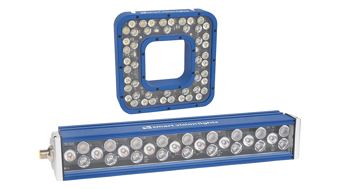
Figure 2: A new series of tunable field of view lights features three independently adjustable beam angle lighting channels. When used with an app, lighting channels can be set to produce unique beam angle combinations that are optimizable for a wide range of field of view requirements. Image source: Smart Vision Lights (Click on the image to enlarge.)
To provide plug-and-play solutions that work with adaptive machine vision systems, many companies have designed prebuilt vision systems. Component-based vision solutions can offer the same benefits in addition to future proofing vision systems. Compared to prebuilt, component-based systems are flexible, changing with needs or technology.
For example, increasing processing power in an advanced vision inspection system may help catch subtle changes over time from machine wear to improve the system. Prebuilt systems are difficult or impossible to upgrade and may have limited or heavily rely on external lighting sources. When looking into adaptive intelligent machine vision solutions consider the following:
- Scalability
- Flexibility
- Processing limitations
- Lighting solutions
- The speed at which technology is moving
A common theme in industry is to do more with less. Single lines are handling multiple products, packages, and processes. Using an advanced vision system with adaptive lighting can change its FOV dynamically to adjust to needs and real-time data. For example, a 10-degree lens can provide maximum projection over a narrow area. For larger areas a wide 50-degree lens will work. Advanced solutions can mix and match a row of three LEDs with 10-, 30-, and 50-degree lenses to achieve an even, uniform FOV between 10 and 50 degrees. This flexibility works well in packaging lines with various sizes of packages. Adaptive light can adjust to the height of each box to reduce misread labels.
Another application is in machine-to-machine dispensing inspection, such as spraying paint or applying adhesives. The constant movement requires an adaptive intelligent system that can work to document, track, and verify that processes are done within specification without consuming takt times or floor space. Inspection processes may also require high-resolution images to detect small imperfections.
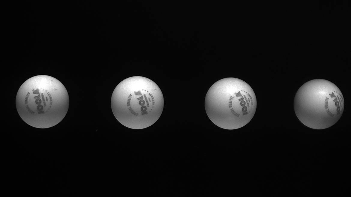
Figure 3: Using an advanced vision lighting solution, the author fired a PingPong ball at about 100 miles per hour through an 8 inch FOV to get this image. The light was strobed in overdrive with four 10 uS pulses spaced at 1.5 mS apart. The ball is in focus, and the lettering and logo are legible. Image source: Smart Vision Lights (Click on the image to enlarge.)
Line Scan Imaging Lighting Challenges
Advanced vision and inspection processes are driving an increase in camera resolution. As camera resolution increases, pixel sizes generally decrease. Smaller pixels are often associated with a reduced full well capacity (a pixel’s ability to store a photogenerated charge before introducing saturation). It is possible to increase light sensitivity by increasing the gain to compensate, but this also amplifies image noise. As pixel size shrinks and frame rates grow, companies need technology that can keep pace with other machine vision technology.
To maintain quality at higher speeds and light intensities, larger pixels can provide a greater full well capacity. Line scan cameras are often associated with larger pixels and greater light intensity to capture a single line at high rates of speed. The challenge is that light doesn’t follow a line, so some light is lost, making FOV important. Also, decreasing FOV increases magnification. Without an adaptive lens, a smaller FOV requires a proportionally higher light intensity. Small FOVs in some line scan cameras are impractical for increasing light intensity.
In continuous applications, an area scan camera could increase lighting intensity to capture a section of a conveyor, shut off, and scan again before missing a section that has passed. For a line scan camera to accomplish this, it would have to scan continuously. The line scan camera’s LEDs would not have an off cycle. For inspection applications where parts are continuously moving, line scan cameras are often a cost-effective solution compared to area scanning cameras. However, without adaptive intelligent vision solutions, and depending on speeds and FOV, line scan cameras can become impractical.
To solve this challenge, companies may opt to use a double-bar line light. These types of products, with smart features, are a combination of the first two challenges that work together seamlessly to provide the FOV and intensities necessary to keep line scan cameras as a practical, cost-effective solution. Additionally, if an area scan camera is used, or later upgraded to, lighting is easy to adapt to the new technology. A double-bar light can connect through Bluetooth to change intensity, FOV, and more as lines evolve over time.
As industry demands higher speeds, and more for less, machine vision provides a solution. While researching solutions for your application, make sure to consider the challenges around light intensity, FOV, and line scan cameras. Look for smart lighting solutions that can handle and adapt the speed of production and changing technology. Flexible hardware with component-based adaptive intelligent software will help keep your company on the leading edge of machine vision solutions.
Looking for a reprint of this article?
From high-res PDFs to custom plaques, order your copy today!


