Materials Testing
The Relationship Between Residual Stress State and Quality
Designing in, manufacturing for, and measuring residual stresses may be the most effective way to produce quality parts.
Does residual stress affect quality? The short answer is “yes.” The better question is, “How does residual stress affect quality?” This article will show that planning, manufacturing in, and evaluating residual stresses will result in a better product that meets specifications, performs better, and meets expected lifetimes.
What Are Residual Stresses?
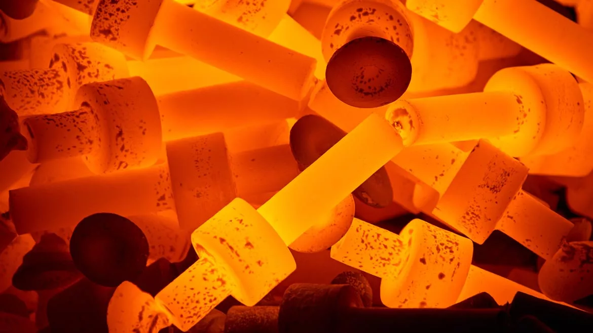
Residual stresses are those stresses that exist when all external loads/forces are removed. They are also called “locked-in” stresses. These stresses form when a part is plastically deformed by mechanical, thermal, chemical or a combination of these forces. In other words, almost anything you do to a part introduces and/or changes the residual stress state.
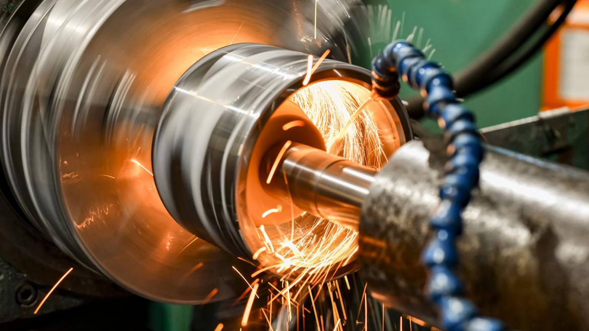
Image Source: Adobe Stock
Tensile stresses attempt to pull the part apart, while compressive stresses attempt to push the part together. To compound the issue, residual stresses add to loading stresses to produce a total stress in the part. Keep in mind that stresses must balance to prevent the part from distorting or cracking.
The good news is we can use modeling to predict residual stresses. We can also control or intentionally induce residual stresses during the manufacturing process.[1] In most cases, outer surface compressive stresses balanced by tensile stresses in the core can potentially protect parts from premature failures and extend part lifetime.
Any manufacturing process that moves, removes layers/sections of, or shapes a part changes the residual stress state. Common manufacturing processes such as casting, forging, welding, machining, grinding, stamping, and thermal treatments result in residual stresses. The final product is a compilation of the changes in stress that occur at each step of the process. Keep in mind that incoming stock also has residual stresses. Depending on the initial residual stress state and the changes that occur at each step in a process, some parts fail before the manufacture is complete.
How Can We Design and Build in Beneficial Residual Stresses?
The final, optimal residual stress state often starts with the design process. Removing stress risers (notches, sharp angles, etc.), selecting appropriate alloys for the service conditions, and calculating stresses across the part based on applied loads during service are critical to designing a part that will survive the part’s expected life. Traditional finite element analysis (FEA) can calculate the expected stresses on a part relative to the dimensions, alloy, and applied stresses found in service, but is frequently limited because it does not account for residual stresses or microstructural variability. Advanced FEA calculations are preferred because they can also take these factors into account.[2] These factors can be controlled in the manufacturing process.
Once the design is completed, manufacturing can begin. Typically, each step of the process results in a change in residual stress. Since the stress state change at each step is also affected by stresses present before an operation, distortion and cracking may result. In these cases, it is imperative that the origin of the problem be identified and corrected. Measuring residual stresses nondestructively at the beginning of and between each manufacturing step may identify the cause of the failure. Factors such as a change in incoming material or a failure/degradation of equipment used in the manufacture may be isolated by nondestructive residual stress measurements. Examples of process-line failures include the dulling of machining/grinding bits and failure of induction coils. Both type failures would result in a different residual stress state compared to those generated by optimal equipment parameters.
Once manufacturing is completed, the inspection process may identify faulty parts. Simply checking chemistry and mechanical properties do not ensure that parts will last their intended lifetime. On parts that are safety-critical or would require high-cost repair/replacement of equipment/systems, measurement of residual stresses may be the best way to limit liability and produce quality parts.
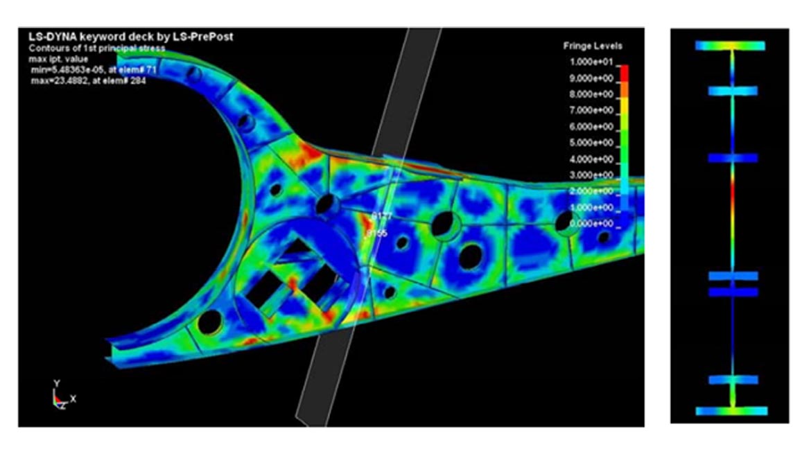
Source: Figure 1: [3] Ball, Dale, Thomas Limer, and Ronald Bridges. "A case study on the application of ICME in aircraft design." 53rd AIAA/ASME/ASCE/AHS/ASC Structures, Structural Dynamics and Materials Conference 20th AIAA/ASME/AHS Adaptive Structures Conference 14th AIAA. 2012.
How Do We Know if We Have Been Successful?
Measuring residual stresses can be time-consuming and adds to the cost of a part. However, the return on investment may quickly be realized when parts with detrimental stresses are identified early in the manufacturing process. There are many ways to measure residual stresses, so selecting the appropriate method is the best way to efficiently inspect and remove faulty parts. These measurements can be divided into nondestructive or destructive.[4]
Nondestructive techniques are the first line of defense when stresses need to be checked at intermediate steps in the manufacturing process, a limited number of parts are produced, the product is very costly, or the part is a safety-critical component. Techniques such as ultrasonic, Barkhausen Noise, and diffraction measurements can be nondestructive. Of these, only X-ray, synchrotron, and neutron diffraction are direct measurements of strain. Ultrasonic and Barkhausen Noise measurements require a calibration sample of the same alloy with the same microstructure. Furthermore, Barkhausen Noise is limited to use on ferro-magnetic materials.
Since synchrotron and neutron diffraction require a high-energy source such as a nuclear reactor, X-ray diffraction (XRD) is a practical choice for nondestructive surface measurements that are precise. The XRD technique also provides information about sample condition in addition to the stress level. The diffraction peak intensity, width, and location can provide information about grain size, plastic strain, and phases present. This information is qualitative but can be quantitative if calibration samples are used. The XRD technique is also an excellent comparison tool. For example, the residual stress value and the diffraction peak width can help determine if a new stress relief process is effective compared to no stress relief or a different thermal process.
After a part is manufactured, the residual stress state should again be checked to help ensure a quality part that will perform as expected. Again, nondestructive or destructive techniques are available. In cases where many parts are made, statistical sampling may be used to qualify each lot. Destructive techniques such as sectioning, splitting, contour method, or hole-drilling techniques may be good options to characterize the residual stresses in the manufactured part. XRD is a good option when nondestructive techniques are required. It is important to understand what each of these techniques is measuring to know if the result provides the required information. The destructive techniques typically regard a part as a homogenous, monolithic material. Residual stress results are calculated on a macroscopic scale. In contrast, the XRD technique can provide microstrain information along with phase-specific stress levels. For example, a steel part that has an austenitic (low yield stress) and a martensitic (high yield stress) phase can be measured by XRD to determine the residual stress in each phase. This capability is important when mechanical requirements require a specific yield stress for the part.
The residual stresses at the surface may dictate whether a part will perform properly. In some cases, it is important to determine the stress versus depth profile. This profile is usually destructive or semi-destructive depending on the part and the technique used. Shot peening should put the outer surface into compression with increased compression just beneath the surface. The stresses then fade at some depth to tensile stresses to maintain balance. If the tensile stresses are deep and low enough, the part is usually protected from premature failure in service. Another classic example of the stress profile being critical comes from grinding operations. In the figure below, the surface stresses are similar regardless of the grinding technique used. Gentle grinding provides the best stress profile, while abusive grinding results in a tensile spike near the surface. When abusively ground parts are put into service, failure is often the outcome. Therefore, it is important to measure stress versus depth on parts that may be subjected to abusive grinding or machining.
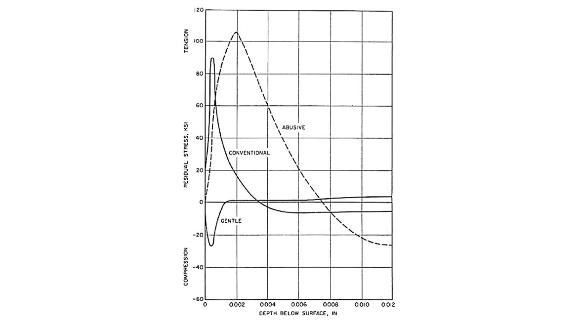
Source: Figure 2: [5] Residual Stress Measurement by X-ray Diffraction-SAE HS-784. SAE International, 2003.
Residual Stresses Can Be the Quality Hero in Manufacturing!
Designing in, manufacturing for, and measuring residual stresses may be the most effective way to produce quality parts. When residual stresses are designed and manufactured in correctly, and the desired stress state is confirmed, parts are often produced efficiently and operate in service optimally. Nondestructive and destructive techniques exist to quantify the residual stresses before, during, and after manufacture. The cost of making residual stress measurements is often negated by quick return on investment when costly delays, repairs or replacements are avoided. Let residual stress management be your hero in producing quality parts.
References
[1] David Furrer, “Residual Stress: Both Friend and Foe”, p. 29-34, Adv. Materials and Processes, Sept. 2020
[2] Matt Watkins, “Efficient Shaping or Reshaping of Complex 3D Parts Using Engineered Residual Stress”, Residual Stress Summit 2017, UDRI, Dayton, OH
[3] Ball, Dale, Thomas Limer, and Ronald Bridges. "A case study on the application of ICME in aircraft design." 53rd AIAA/ASME/ASCE/AHS/ASC Structures, Structural Dynamics and Materials Conference 20th AIAA/ASME/AHS Adaptive Structures Conference 14th AIAA. 2012.
[4] Gary S. Schajer, ed., Practical Residual Stress Measurement Methods, Wiley, 2013
[5] Residual Stress Measurement by X-ray Diffraction-SAE HS-784. SAE International, 2003.
Looking for a reprint of this article?
From high-res PDFs to custom plaques, order your copy today!


