Test & Inspection
Screw Thread Inspection: Options, Dimensions and Decisions
Gaging systems can fundamentally be categorized into three groups.

All Images Source: Johnson Gage
.webp?t=1719268912&width=1080)
The screw was initially used to press oil from olives, extract juice from grapes and redirect water from rivers. During the First American Industrial Revolution (1760-1840) screw drives were incorporated into lathes, various thread forms were being utilized and threaded fasteners were starting to be manufactured on a large scale. During the Second American Revolution (1870-1914) interchangeable parts became critical to production, assembly, and repair. Screw threads were a fixture in the design of interchangeable assemblies. World War I and II uncovered the need for a higher degree of standardization for both thread classes of fit and inspection methods.
Many include the first rule of a threaded assembly is the external and internal thread must go together. After going together, the second rule of the assembly is it must stay together and perform its intended design requirements. Inherent in this screw thread assembly is the proper size and form of both components. While there have been organizations that have historically participated in the Standardization of Screw Threads, ASME B1 Screw Thread Committee has become the organization to hold, update and curate the standards. The ASME B1 Screw Thread Standards Committee publish two documents that outline the design of various thread forms such as Unified 60 Degree, Metric 60 Degree, ACME, BUTTRESS, and Tapered pipe threads. They also publish critical industry documents on Thread Gaging and measurement uncertainty. One essential document to the Screw Thread Industry is ASME B1.3, Screw Thread Gaging Systems for Acceptability. This document is the standard to categorize which screw thread gaging system is suitable for determining the dimensional acceptability of the size and/or form of an external or internal screw thread.
THREAD GAGE OPTIONS
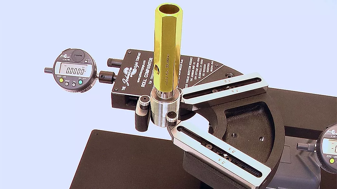
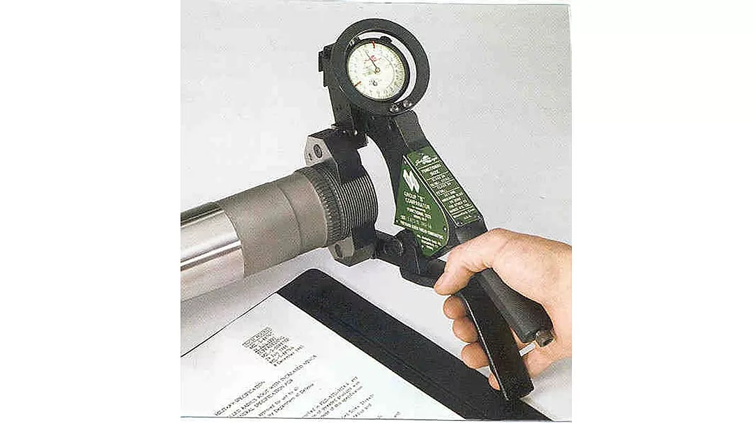
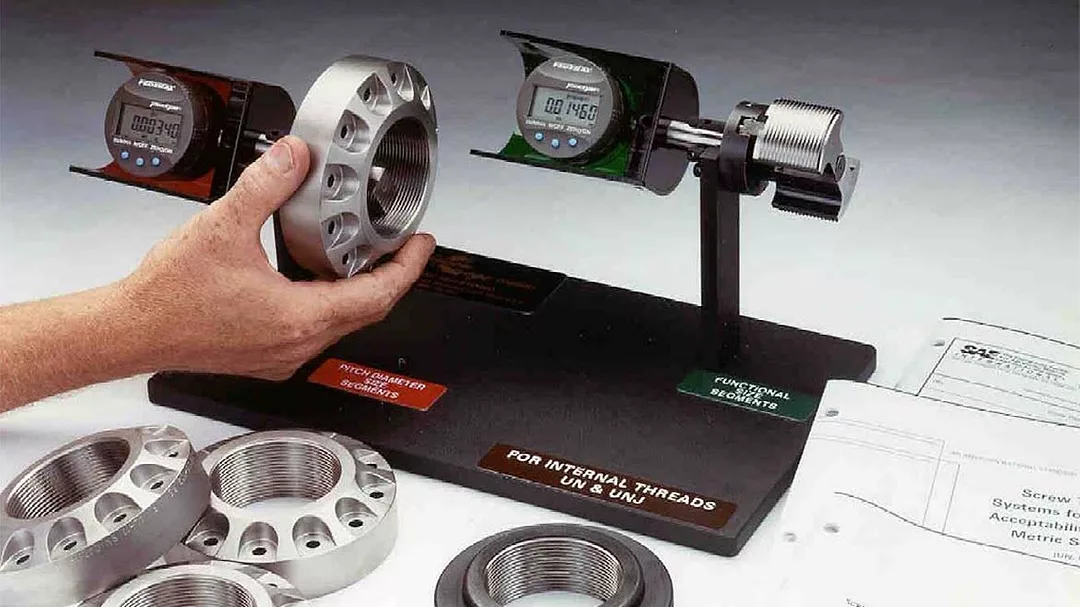
There are gaging options available for screw thread inspection. Gaging systems can fundamentally be categorized into three groups. The first group of gage systems includes the least expensive gage system. These gages typically consist of a fixed limit gage(s) that include both a GO and NOT GO. Fixed limit gages are often used as a functional gage, simple but effective determination of the pass/fail criteria. Unfortunately, they provide limited actionable data. The second group of gages includes the mid-priced inspection system that measures and provides data from a direct contact style of measurement. These systems include the Indicating type gage and are typically used for actions such as: set-up, process control, dimensional inspection, size and/or form analysis. The next level includes the typically more expensive non-contact style measurement systems. These systems are often employed facility wide to include additional Metrology needs. Examples of systems listed in ASME B1.3 include Optical Comparators, Profile Tracing Machines, Linear Measuring Machines and Coordinate Measuring machines. These systems can provide supplemental information related to specific thread features that when combined with traditional thread gaging create a robust thread inspection system.
THREAD SIZE
A screw thread is a continuous projecting helical ridge on a cylindrical or conical surface. It consists of diameters, angle, helix and a lead. Each screw thread has a condition where a feature of size contains the most amount of material within the required limits of size. The diameter associated with the most material is the Maximum Material condition for Size and Form. The Screw Thread industry identifies this as “GO” / Functional Diameter. By definition the Functional Diameter is the cumulative effect of variations from the specified thread profile. Variations may include Pitch Diameter Size, Angle, Lead, Roundness, and Taper. Gaging for this condition follows the first condition of the Taylor Principle: Maximum Material limits of as many elements or dimensions as practical should be incorporated in the GO Gage. ASME B1.3 Table 1 (External Threads) and Table 2 (Internal Threads) lists the gaging to determine dimensional acceptability of Maximum Material / “GO” Functional Diameter. Functional Gaging is the system of using thread gages of near perfect form at the maximum material limits to simulate the contact interface of the mating part. Example: External Thread Gage Maximum Material / GO Functional profile

After determining acceptability of GO Functional Diameter and deducing that the thread will assemble with its mating part the next step is to assure the part has enough material to perform its intended design function. This condition, Minimum Material Condition, is where the feature of size contains the least amount of material within the required limits of size. Gaging a thread for minimum material follows the second condition of the Taylor Principle: Minimum Material limits of such elements or dimensions may be gaged only as individual (single) elements. ASME B1.3 Table 1 (External Threads) and Table 2 (Internal Threads) lists acceptable gages to determine Screw Thread dimensional acceptability for Minimum Material / Pitch Diameter or Groove Diameter. Minimum Material inspection is the system of using a thread gage of limited contact to inspect size only, intentionally leaving out inspection of the thread form.

THREAD FORM
The thread angle is the included angle formed by two adjacent flanks in an axial place.
ASME B1.7 – 2007 page 20

The Lead of a thread is the axial distance between two corresponding points on a thread. When a thread is rotated about its axis with respect to its mating thread, the lead is the axial distance moved by the part in relation to the amount of angular rotation.
ASME B1.7 – 2007 page 10

Roundness, oval: 2 points at 180 degree half the difference between maximum and minimum pitch diameters of the pitch cylinder circumference. Roundness, multilobe: 3 points at 120 degree half the distance between maximum material and minimum material variations in positions of one side of as equilateral triangle which envelopes the pitch cylinder and the theoretical positions of that side as this enveloping triangle is rotated around the circumference of the pitch cylinder.
ASME B1.7 – 2007 page 17

Straightness of a screw thread is a condition where the pitch cylinder forms a straight line. When the cylinder does not adhere to a straight line it is considered to have either a back or front taper condition.

ACCEPTABLE SIZE and FORM
A Screw Thread is determined to be dimensionally acceptable when the Functional and Pitch Diameter Size and Thread Form is within the Pitch Diameter limit of Size. Functional Diameter and Pitch Diameter share the same tolerance and both must be within the limits of size. On a perfectly formed screw thread, the Functional Diameter and Pitch Diameter will be equal in size. When evaluating a screw thread and the Functional Diameter is equal to the Pitch Diameter (or relatively close) further thread form evaluation is unnecessary.

A diameter difference between the Functional and Pitch Diameter is called Cumulative Thread Element Variation Differential. This differential consists of thread form error. The Cumulative Thread Element Differential is derived by subtracting the Maximum Material 9 and Minimum Material size. This represents the diametral effect of the total amount of thread form variation. This data point is calculated and expressed as a percentage of the pitch diameter tolerance. The total thread form variation must be contained within the pitch diameter tolerance.

While some specifications and certain thread categories specify an acceptable amount of Cumulative Thread Element Differential, most products simply require the differential to be contained within the Pitch Diameter tolerance. In our current data driven world there is a growing trend of quality, engineering and manufacturing individuals turning differential into a call for action. The rationale is that a simple analysis of the Cumulative Thread Element Differential value into Single Thread Element Variation Differential can assist in machine setup, tool analysis, process control, cost reduction, first article inspection and the ability to stand out in front of your customer. 10 ASME B1.2 identifies the Differential Segment or Roll Gage that when used in combination with a GO Functional Indicating Gage and the Minimum Material indicating gage will perform a Single Thread Element Variation analysis. This analysis will determine the effects of Roundness, Taper of the Pitch Cylinder, Lead, and Flank errors reflected as a percentage of the Pitch Diameter tolerance.

DECISIONS
There are many other elements and factors related to the Screw Thread and Screw Thread Gaging that were not able to be included in this article. Even though the Screw is one of the six simple machines production and measurement can remain a challenge. Critical to the selection of any screw thread inspection process is understanding the application, understanding the acceptance criteria, conformance with the standards, and meeting or exceeding customer expectations. Your choice includes gaging options but keep in mind the parts always need to go together and stay together and preform its intended design function. Inspect accordingly.
Looking for a reprint of this article?
From high-res PDFs to custom plaques, order your copy today!


